MSD
TM
Series
© Copyright 2018 Fluid Equipment Development Company | www.fedco-usa.com
- 28 -
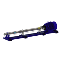
Figure 43 - Flex Coupling Installation
10. Slide the exible coupling onto the motor
shaft until the end of the motor shaft is ush
with the end of the motor half of the exible
coupling.
NOTES: The motor shaft and its key should
NOT be touching the plates of the exible cou-
pling disc pack. Ensure that the motor key does
not slide out of place or project past the end of
the motor shaft.
11. Install the exible coupling set screws and
tighten.
NOTES: Set screws are only on the motor side
of the exible coupling. No set screws should
be installed on the pump shaft side.
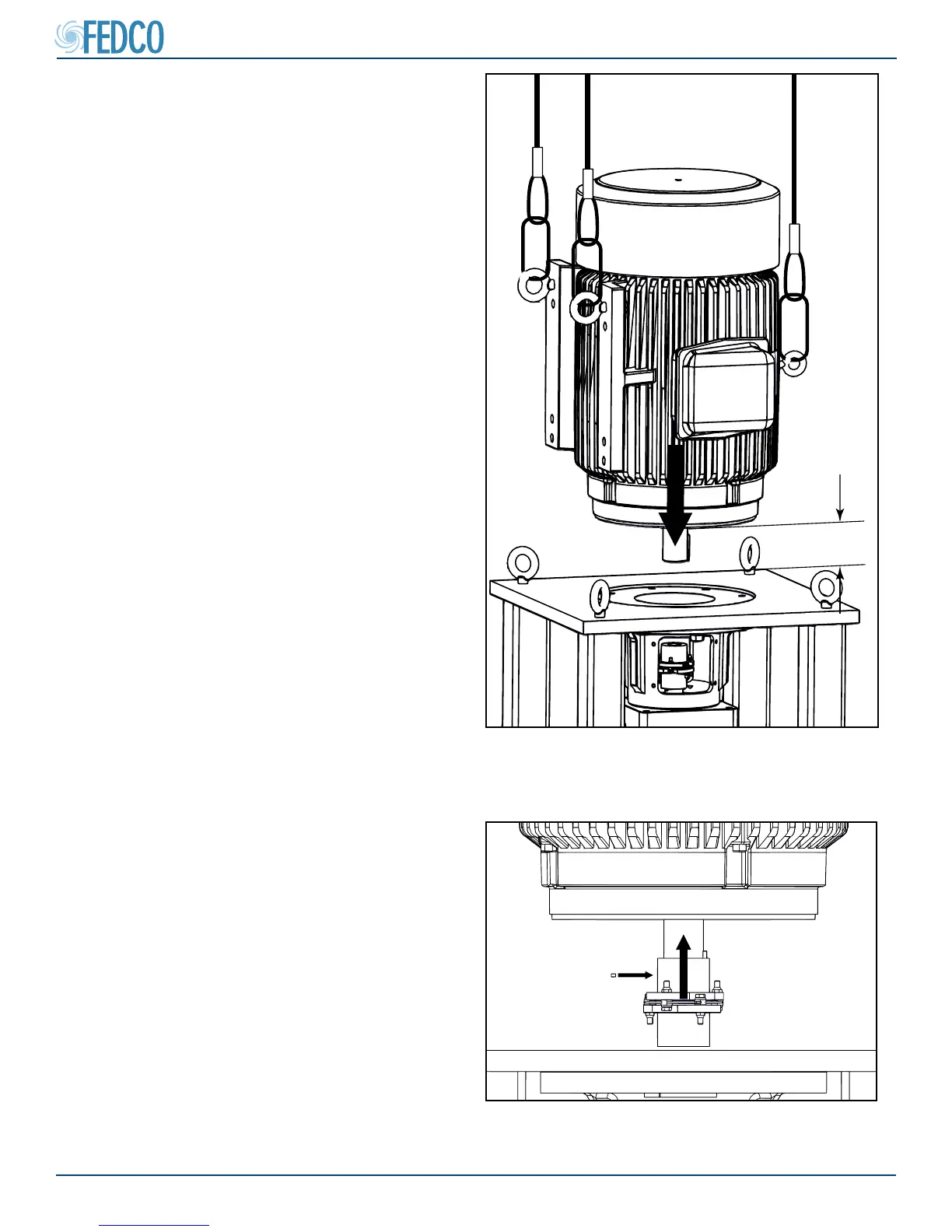
12”
Figure 42 - Placing Vertical Motor In Mounting
Position
8. Clean the motor ange face with a clean lint
free cloth to remove any foreign matter, rust
or protective coating and place the motor in
its mounting position.
9. Using suitable lifting equipment, raise the
motor approximately twelve (12”) inches
above the pump stand and pump.
NOTES: Motor key should still be installed from
the ex coupling check.
Pump Assembly Continued