EN
18
Unpacking
• Check all parts for shipping damage.
If damage has occurred it should be reclaimed directly
when delivered.
• Check the delivery for completeness.
Immediately report missing parts to the dealer.
Scope of delivery
1 x planer and thicknesser
1 x angle fence
1 x dust chute
1 x 4 mm hex wrench
1 x crank for the height adjustment of the thicknesser
table
2 x drive belt
1 x push stick
1 x dust chute gear unit ( 640 and PF204 version only).
6 INSTALLATION
Danger!
Modifi cation of the machine or use of parts not
tested and approved by the equipment manufacturer
can cause unforeseen damage.
• Assemble machine exactly as per these instructions.
• Use only the parts supplied with the machine as standard
equipment.
• Do not make changes to any of the parts.
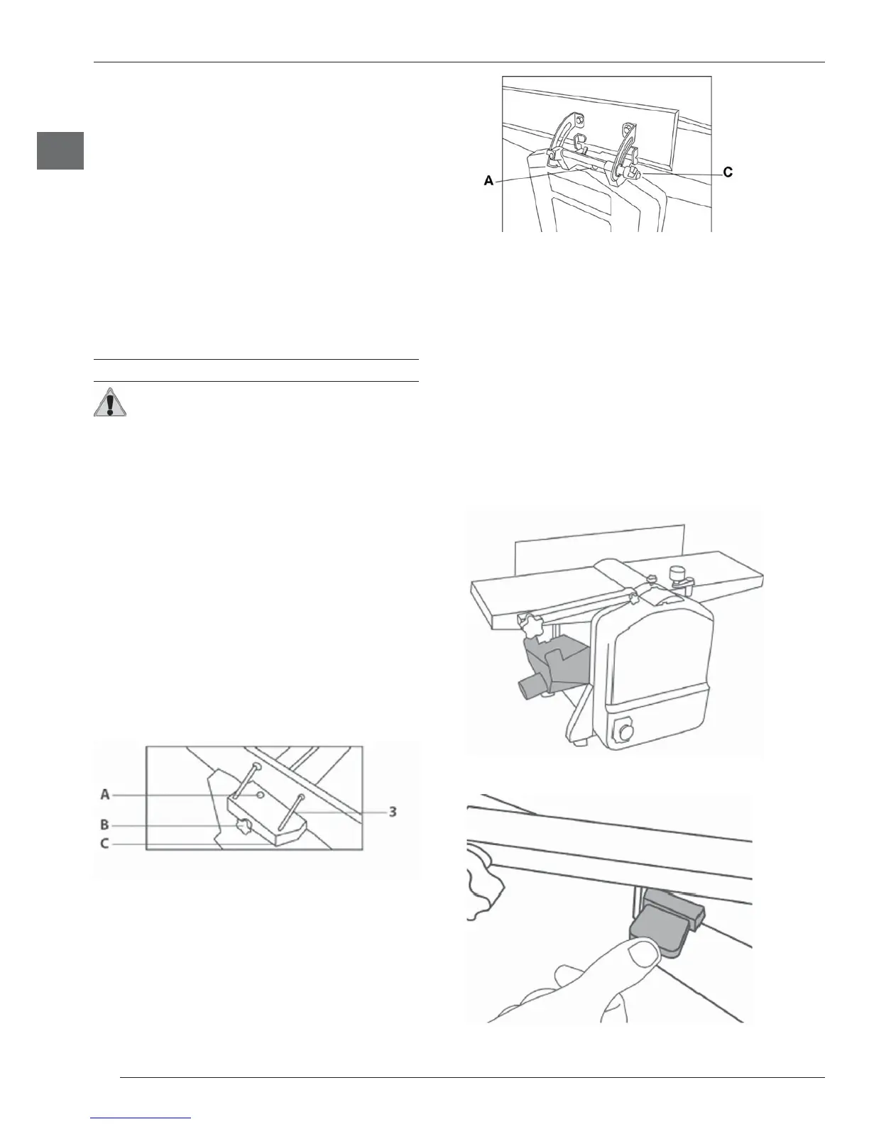
6.1 Angle fence installation
Required screws and washers are already mounted to the
machine.
Models 630, PF204, PF150
• Insert the screw into slot A.
• Locate the angle fence on screw B.
• First securely tighten screw A, then screw C.
• The angle adjustment is made with screw C in accordance
to the angle fence scale 3.
Model 640
• Tighten the screws A
• Use screw C for angle adjustment using the scale 3 on
the angle support guide.
6.2 Dust chute installation
The dust chute 1 has to be connected properly with the
tool.
In case of improper installation, a limit switch prevents the
machine from starting (see Safety Devices).
Use as planer
• Lift up the blade guard 4 so that the longitudinal holes on
both sides of the planer table 5 are accessible.
• Pull out the keys on both sides of the dust chute 1.
• Move down the thicknesser table 12 to the lowest position
using the thicknesser table height adjustment 7.
• Insert the dust chute 1.
• The dust chute 1 has to be positioned so that both keys
are in line with the longitudinal holes.
• Push both keys in the holes.