10 ferrismowers.com
Callout Hazard Meaning
D Rollover hazard
E Fire hazard
F Amputation - hand in blade
G Amputation - foot in blade
H Thrown objects
I Pinch point
Safety Alert Symbol and Signal Words
The safety alert symbol ( ) is used to identify safety
information about hazards that can result in personal injury. A
signal word (DANGER, WARNING, or CAUTION) is used with
the alert symbol to indicate the likelihood and the potential
severity of injury. In addition, a hazard symbol may be used to
represent the type of hazard.
DANGERindicates a hazard which, if not avoided,will
result in death or serious injury.
WARNINGindicates a hazard which, if not
avoided,could result in death or serious injury.
CAUTIONindicates a hazard which, if not
avoided,could result in minor or moderate injury.
NOTICEindicates a situation thatcould result in damage
to the product.
Safety Interlock System
This unit is equipped with safety interlock mechanisms. These
safety systems are present for your safety, do not attempt to
bypass safety interlock mechanisms, and never tamper with
safety devices. Check their operation regularly.
Test 1 - Blades should SHUT OFF if:
• The operator releases the blade engagement lever.
Test 2 - Blades SHOULD turn on if:
• Operator releases the blade engagement lockout and
depresses the blade engagement lever.
Test 3 - Blade Brake Check
Mower blades and the mower deck drive belt should come
to a complete stop within seven (7) seconds after the blade
engagement lever is released. If the mower deck drive belt
does not stop within seven (7) seconds, see your dealer.
Features and Controls
Control Locations & Functions
The information below briefly describes the function of
individual controls. Starting, stopping, driving, and mowing
require the combined use of several controls applied in
specific sequences. To learn what combination and sequence
of controls to use for various tasks see the Operation section.
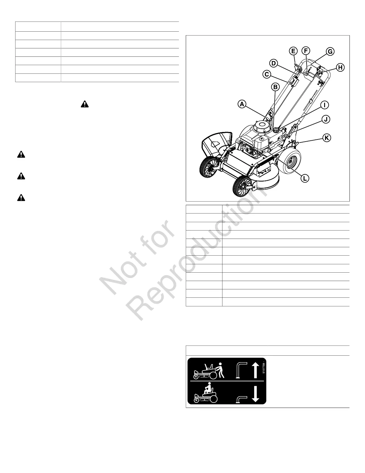
Control Locations
3
A Recoil Starter Handle
B Transmission Release Lever
C Throttle Control and Engine Shut Down Lever
D Blade Engagement Lever Lockout
E Blade Engagement Lever
F Maximum Forward Speed Control Lever
G Forward Motion Control Lever
H Reverse Motion Control Lever
I Fuel Tank Cap
J Choke
K Cut Height Adjustment Lever
L Fuel Shutoff Valve
Recoil Starter Handle: The recoil starter handle is used to
start the engine.
Transmission Release Lever:
Icon Control Name
Transmission Release Levers
This unit is equipped with a transmission release lever. The
transmission release lever deactivates the transaxle so that
the unit can be pushed by hand. SeePushing the Unit by
Handfor operational information.
 Loading...