23
31
3. Position the forward motion control lever so that the large
part of the handle is on the side of the machine that the
operator prefers and install the hardware to secure it back
in place.
Note:If your unit has washers installed between the forward
motion control lever and the upper motion control bracket,
the washers must be re-installed in the same position when
assembling
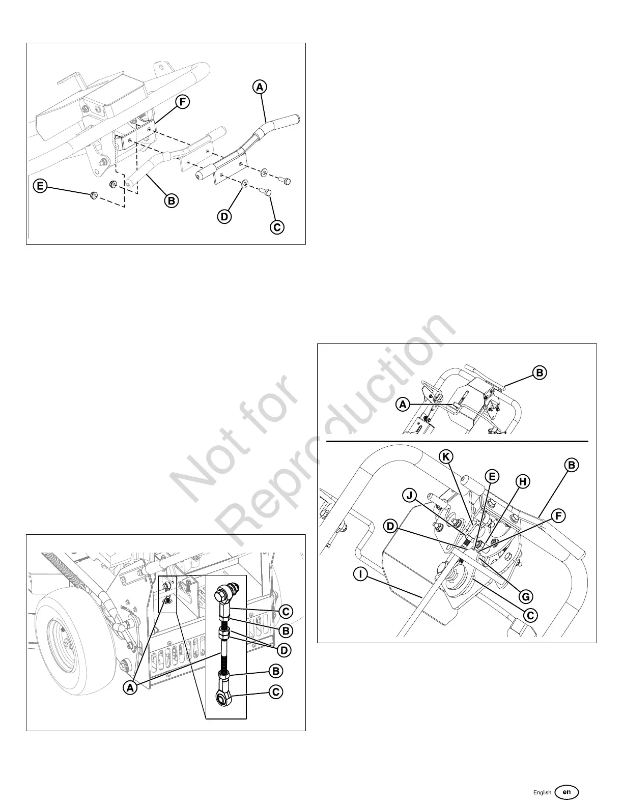
Neutral Adjustment
If the unit "creeps" when the operator is not touching the
controls, it may be necessary to adjust the neutral adjustment
linkage rod (A, Figure32).
Prior to making any adjustments you should always check
that nothing is binding when the forward and reverse speed
control levers are moving through their full range of motions.
If there is any binding in the controls that issue must first be
addressed before adjusting the neutral.
1. Locate the neutral linkage rod (A, Figure32) on the left
rear of the engine deck.
32
2. Chock the front wheels of the unit. Raise the rear wheels
of the unit of the ground and secure the unit with jack
stands.
3. Start the engine and adjust the throttle control to the
SLOW position. SeeStarting the Enginesection for
proper starting instructions.
4. Loosen the jam nuts (B) that are tightened against the
ball joints (C).
5. Using a wrench, turn the double nut assembly (D) on the
neutral linkage rod in whatever direction is necessary to
slow the rotation of the tire.
6. Once the tire rotation stops, tighten the jam nuts against
the ball joints
Forward Speed Control Lever Placement
Adjustment
The forward speed control lever can be placed in four (4)
different positions to allow the operator to customize the
maximum overall forward speed of the unit.
1. Drive the unit to level, open area that is clear of
obstructions.
2. With the mower blades off, place the forward speed
control lever (A, Figure33) in the first setting (labelled 1)
and then press the forward motion control lever (B) down
and forward to make the unit move forward.
33
3. Set the forward speed control lever in the second setting
(labelled 2); the unit should now move faster. Continue
this process for the third and fourth settings (labelled 3
and 4, respectively). With each higher numbered setting
the unit should drive faster. If it does not, continue with
step #4.
4. Park the machine on a flat, level surface such as a
concrete floor. Move the throttle control and engine shut
down lever to the shut down position and wait for the
engine and all moving parts to stop.
 Loading...