25
10. Have an assistant release the blade engagement lever
lockout and depress the blade engagement lever. This
will pull the blade brake (K) away from the discharge side
spindle pulley (L).
11. Remove the spindle drive belt from the trim side spindle
sprocket (M) and then the discharge side spindle sprocket
(N) and then remove the belt from the unit.
12. Install a new spindle drive belt onto the discharge side
spindle sprocket and make sure that the belt is properly
seated in the teeth of the sprocket.
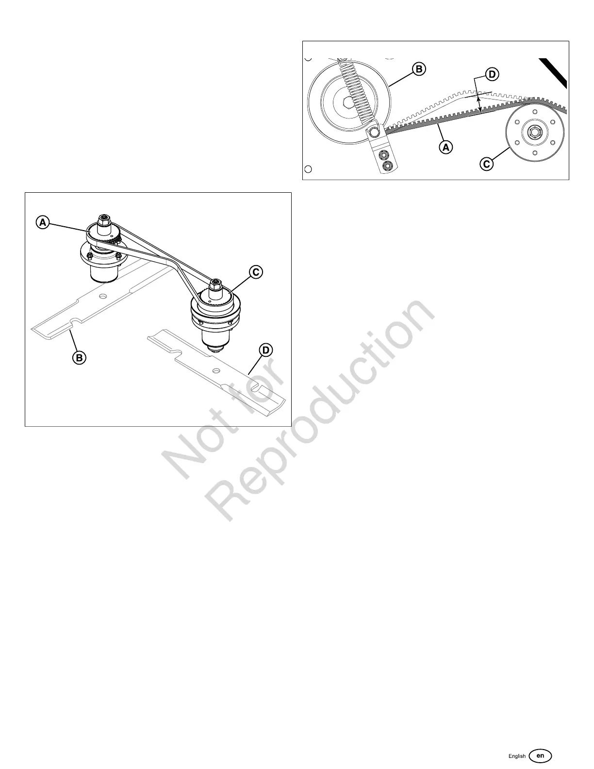
13. Rotate the discharge side spindle sprocket (A,37) so that
the blade (B) is facing front to back.
37
14. Rotate the trim side spindle sprocket (C) so that the
blade (D) is facing side to side and then install the belt
(G, Figure35) on the left hand spindle sprocket (M) and
make sure that the belt is properly seated in the teeth of
the sprocket.
15. Make sure that the back side of the belt is contacting the
face of the rear stationary idler pulley (O) and the front
adjustable pulley (F).
16. Slide the front adjustable pulley towards the back until
it tensions the spindle drive belt and then tighten the
mounting hardware (E) to secure it in place.
17. Check the tension of the belt (A, Figure38) by pressing
on the center of the length of belt between the discharge
side spindle (B) and the front adjustable pulley (C). While
pushing with 3 lbs (1,4 kg) of force the belt should deflect
3/16" (0,5 cm) (D). If it does not, make adjustments to the
position of the front adjustable pulley until the correct belt
tension is achieved.
38
18. Install the front spring mounting hardware (I, Figure35)
into the bracket (J).
19. Using a spring puller tool carefully install the spring (H)
onto the front spring mounting hardware.
20. Install the spindle pulley (C, Figure36) onto the trim side
spindle shaft (D) making sure to properly seat the key
way of the pulley onto the key. Install the washer (B)
with the concave side of the washer towards the pulley.
Install the pulley bolt (A) hand tight to hold the washer
and pulley in place.
21. Tighten the pulley bolt to 50 - 60 ft. lbs. (68 - 81 Nm) of
torque while holding onto the blade mounting bolt with a
wrench.
22. Have an assistant release the blade engagement lever.
This will move the tensioning pulley (B, Figure35) away
from the belt path allowing you to install the belt.
23. Install the new mower deck drive belt (A) onto the
crankshaft pulley (D) and the trim side spindle pulley (C)
making sure that the V-side of the belt fits in the grooves
of the pulley and that the back side of the belt contacts
the face of the tensioning pulley (B).
24. Install the mower deck guards.
25. Install the spark plug wire(s) onto the spark plug(s).
26. Start the engine.
27. Release the blade engagement lever lockout and depress
the blade engagement lever and allow the blades to
run for a few moments. Release the blade engagement
lever. The blades should stop rotating within seven (7)
seconds.If the blades do not stop turning in seven
(7) seconds, turn the unit off, remove the unit from
service, and see your dealer.
Changing the Transaxle Drive Belt
Figure40depicts the top of the unit as if the operator was
looking down at it. Some components are hidden for clarity.
1. Release the blade engagement lever to stop the blades
and move the throttle control and engine shut down lever
to the OFF position to stop the engine.
2. Remove the mower deck drive belt from the crankshaft
pulley. SeeChanging the Mower Deck Belts.
3. Remove the transaxle fan guard (A, Figure39) and the
two (2) screws (B).
 Loading...