BLUEHELIX TECH S 45H
35
EN
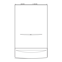
If the room temperature is lower than the required value, it is advisable to set a higher
order curve and vice versa. Proceed by increasing or decreasing in steps of one and
check the result in the room.
fig. 11 - Example of compensation parallel curve offset
Adjustments from Remote Timer Control
A
If the Remote Timer Control (optional) is connected to the boiler, the above ad-
justments are managed according to that given in table 1.
Table. 1
System water pressure adjustment
The filling pressure read on the boiler water gauge with the system cold must be approx
1.0 bar. If the system pressure falls to values below minimum, the boiler stops and fault
F37 is displayed.
Once the system pressure is restored, the boiler will activate the 300-second air venting
cycle indicated on the display by FH.
3. INSTALLATION
3.1 General Instructions
BOILER INSTALLATION MUST ONLY BE PERFORMED BY QUALIFIED PERSON-
NEL, IN ACCORDANCE WITH ALL THE INSTRUCTIONS GIVEN IN THIS TECHNICAL
MANUAL, THE PROVISIONS OF CURRENT LAW, THE PRESCRIPTIONS OF NA-
TIONAL AND LOCAL STANDARDS AND THE RULES OF PROPER WORKMANSHIP.
The unit is designed to operate in a partially protected place according to EN 297/A6,
with minimum temperature of -5°C. The boiler must be installed in a sheltered place, e.g.
under the slope of a roof, inside a balcony or in a protected recess.
The place of installation must be free of flammable materials, objects and dusts or cor-
rosive gases.
The boiler is arranged for wall mounting and comes as standard with a hooking bracket.
Wall fixing must ensure stable and effective support for the generator.
A
If the unit is enclosed in a cabinet or mounted alongside, there must be suffi-
cient space for removing the casing and for normal maintenance activities
3.3 Plumbing connections
Important
B
The safety valve outlet must be connected to a funnel or collection pipe to pre-
vent water spurting onto the floor in case of overpressure in the heating circuit.
Otherwise, if the discharge valve cuts in and floods the room, the boiler manu-
facturer cannot be held liable.
B
Before installation, flush all the pipes of the system thoroughly to remove any
residuals or impurities that could affect proper operation of the unit.
In case of replacement of generators in existing installations, the system must
be completely emptied and cleaned of any sludge and pollutants. For that pur-
pose only use suitable guaranteed products for heating systems (see next sec-
tion), that do not harm metals, plastics or rubber. The manufacturer declines
any liability for damage caused to the generator by failure to properly
clean the system.
Carry out the relevant connections according to the diagram in fig. 12 and the symbols
given on the unit.
fig. 12 - Plumbing connections
1 = System delivery - Ø 3/4”
3 = Gas inlet - Ø 1/2”
5 = System return - Ø 3/4”
Antifreeze system, antifreeze fluids, additives and inhibitors
When necessary, antifreeze fluids, additives and inhibitors can be used only if the man-
ufacturer of such fluids or additives guarantees that they are suitable and do not cause
damage to the exchanger or other components and/or materials of the boiler and system.
Do not use generic antifreeze fluids, additives or inhibitors that are not specific for use in
heating systems and compatible with the materials of the boiler and system.
Water system characteristics
In the presence of water harder than 25° Fr (1°F = 10ppm CaCO
3
), use suitably treated
water in order to avoid possible scaling in the boiler.
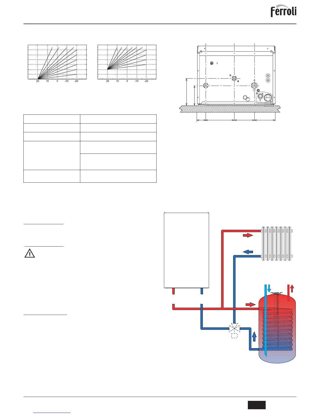
Connection to a storage tank for domestic hot water production
The unit's electronic board is arranged for managing an external storage tank for domes-
tic hot water production. Carry out the plumbing connections according to the diagram of
fig. 13. Carry out the electrical connections as shown on the wiring diagram in fig. 29. At
the next lighting, the boiler control system detects the hot water tank probe and automat-
ically configures the DHW function, activating the display and relevant controls.
fig. 13 - Diagram of connection to external hot water tank
8 Domestic hot water outlet
9 Cold water inlet
10 System delivery - Ø 3/4”
11 System return - Ø 3/4”
95 Diverter valve
Heating temperature setting
Adjustment can be made from the Remote Timer Control menu
and the boiler control panel.
DHW temperature adjustment
Adjustment can be made from the Remote Timer Control menu
and the boiler control panel.
Summer/Winter Switchover
Summer mode has priority over a possible Remote Timer Control
heating demand.
Eco/Comfort selection
On disabling DHW from the Remote Timer Control menu, the
boiler selects the Economy mode. In this condition, the
eco/com-
fort
button (detail 7 - fig. 1) on the boiler panel is disabled.
On enabling DHW from the Remote Timer Control menu, the
boiler selects the Comfort mode. In this condition it is possible
select one of the two modes with the
eco/comfort
button (detail 7
- fig. 1) on the boiler panel.
Sliding Temperature
Both the Remote Timer Control and the boiler card manage Slid-
ing Temperature adjustment: the boiler card Sliding Temperature
has priority.
 Loading...