BLUEHELIX TECH S 45H
37
EN
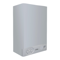
For the connection of separate ducts, fit the unit with the following starting accessory:
fig. 18 - Starting accessory for separate ducts
Before proceeding with installation make sure the maximum permissible length has not
been exceeded, by means of a simple calculation:
1. Completely establish the layout of the system of split flues, including accessories
and outlet terminals.
2. Consult table 6 and identify the losses in m
eq
(equivalent metres) of every compo-
nent, according to the installation position.
3. Check that the sum total of losses is less than or equal to the maximum permissible
length in table 5.
Table. 5 - Max. length separate ducts
Table. 6 - Accessories
Connection to collective flues
fig. 19 - Examples of connection to flues ( = Air / = Fumes)
Table. 7 - Typology
If the boiler is to be connected BLUEHELIX TECH S 45H to a collective flue or a single
flue with natural draught, the flue or chimney must be expressly designed by profession-
ally qualified technical personnel in conformity with the current regulations and be suita-
ble for sealed chamber units equipped with fan.
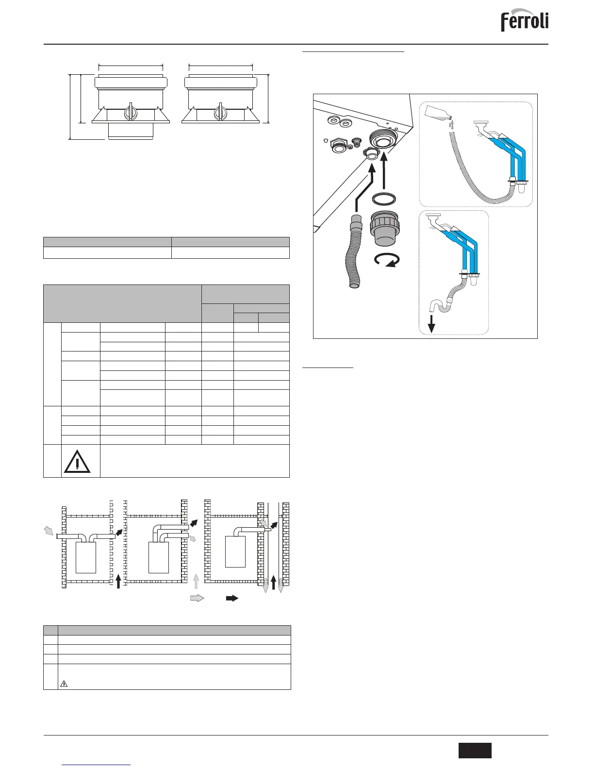
3.7 Condensate drain connection
The boiler has an internal trap for draining condensate. Fit the inspection union A and
the hose B, pressing it in. Fill the air-trap with approximately 0.5 l. of water and connect
the hose to the disposal system
B
ATTENTION: The unit must never be operated with the trap empty!
fig. 20 - Condensate outlet connection
4. SERVICE AND MAINTENANCE
4.1 Adjustments
Gas conversion
The unit can operate on Natural Gas or LPG and is factory-set for use with one of these
two gases, as clearly shown on the packing and on the data plate. Whenever a different
gas to that for which the unit is arranged has to be used, a conversion kit will be required,
proceeding as follows:
1. Remove the front panel (see *** 'Opening the front panel' on page 38 ***).
2. Undo the screw and rotate the control panel (see fig. 21).
3. Unscrew ring C and remove gas pipe A from the gas valve (see fig. 22).
4. Replace nozzle B inserted in the gas pipe with that contained in the conversion kit,
interposing seal D (see fig. 22).
5. Refit gas pipe A and check the tightness of the connection.
6. Apply the label, contained in the conversion kit, near the data plate.
7. Refit the front panel.
8. Modify the parameter for the type of gas:
• put the boiler in standby mode
• press the DHW buttons (details 1 and 2 - fig. 1) for 10 seconds: the display
shows “b01” flashing.
• press the DHW buttons (details 1 or 2 - fig. 1) to set parameter 00 (for operation
with natural gas) or 01 (for operation with LPG).
• press the heating + button (detail 4 - fig. 1) until “b04” flashes on the display.
• press the DHW buttons (details 1 or 2 - fig. 1) to set parameter 200 (for opera-
tion with natural gas) or 190 (for operation with LPG).
• press the heating + button (detail 4 - fig. 1) until “b05” flashes on the display
• press the DHW buttons (details 1 or 2 - fig. 1) to set parameter 200 (for opera-
tion with natural gas) or 190 (for operation with LPG).
• press the DHW buttons (details 1 and 2 - fig. 1) for 10 seconds.
• the boiler will return to standby mode
9. Using a combustion analyser connected to the boiler fume outlet, check that the
CO
2
content in the fumes, with the boiler operating at max. and min. output, matches
that given in the technical data table for the corresponding type of gas.
Max. permissible length
40 m
eq
Losses in m
eq
Air
inlet
Fume exhaust
Vertical Horizontal
Ø 80
PIPE
1 m M/F 1KWMA83W 1.0 1.6 2.0
BEND
45° M/F 1KWMA65W 1.2 1.8
90° M/F 1KWMA01W 1,5 2.0
PIPE SECTION
with test point 1KWMA70W 0.3 0.3
TERMINAL
air, wall 1KWMA85A 2.0 -
fumes, wall with antiwind 1KWMA86A - 5.0
FLUE
Split air/fumes 80/80 010027X0 - 12.0
Fume outlet only Ø80 010026X0 +
1KWMA86U
-4.0
Ø 60
PIPE
1 m M/F 1KWMA89W 6.0
BEND
90° M/F 1KWMA88W 4.5
REDUCTION
80/60 041050X0 5.0
TERMINAL
fumes, wall with antiwind 1KWMA90A 7.0
ATTENTION: CONSIDER THE HIGH PRESSURE LOSSES OF Ø60 ACCESSORIES;
USE THEM ONLY IF NECESSARY AND AT THE LAST FUME EXHAUST SECTION.
Type Description
C2X
Intake and exhaust in common flue (intake and exhaust in same flue)
C4X
Intake and exhaust in common and separate flues , but undergoing similar wind conditions
C8X
Exhaust in single or common flue and wall intake
B3X
Intake from installation room by means of concentric duct (that encloses the exhaust) and exhaust in common
flue with natural draught
IMPORTANT - THE ROOM MUST BE PROVIDED WITH APPROPRIATE VENTILATION
 Loading...