i25 / i29
16
EN
cod. 3541I730 - Rev. 02 - 11/2016
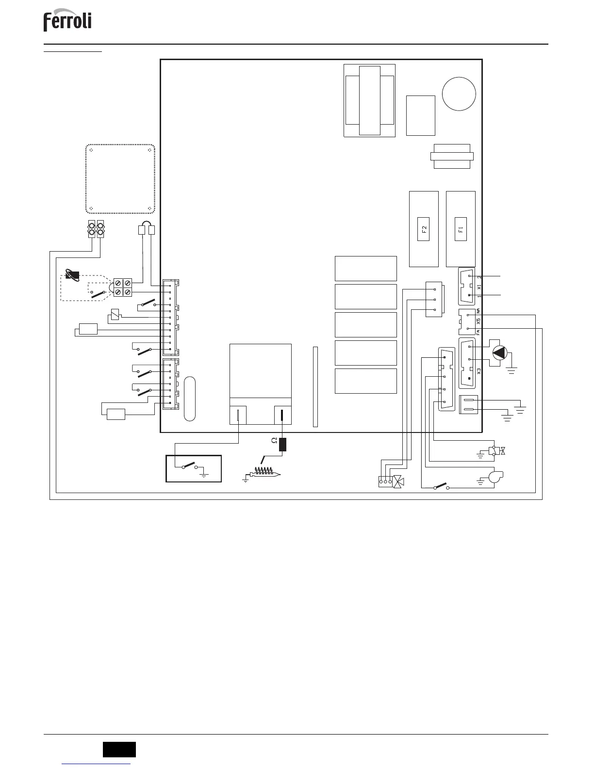
5.6 Wiring diagram
fig. 31 - Wiring diagram
A
Attention: Remove the jumper on the terminal block before connecting the room thermostat or remote timer control.
16 Fan
32 Heating circulating pump
34 C.H. flow temperature sensor
38 Flowswitch
42 DHW temperature sensor
43 Air pressure switch
44 Gas valve
47 Modureg
49 Overheat cut-off thermostat
62 Time clock (not fitted)
72 Room thermostat (not fitted)
81 Ignition and detection electrode
95 Diverting valve
114 Water pressure switch
126 Contact fume thermostat
139 Remote timer control (not fitted)
193 Trap
 Loading...