i25 / i29
8
EN
cod. 3541I730 - Rev. 02 - 11/2016
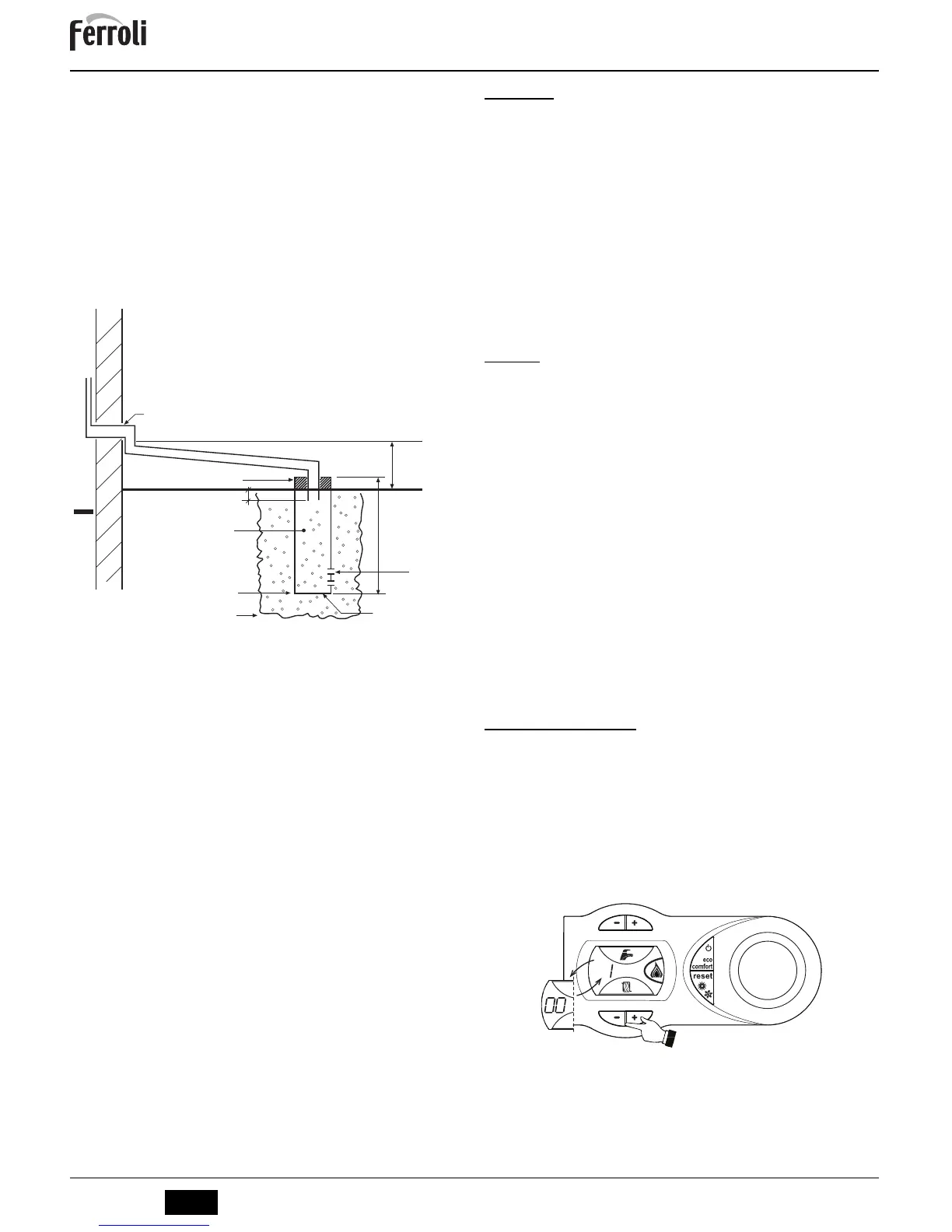
Condensate drain
The condensate should be run inside as far as is practicably possible. For that purpose, use a pipe of at
least 22 mm diameter and a trap with flexible connection supplied
with the unit to facilitate connection
of the condensate drain pipe.
The pipe must be in solvent weld plastic and not in copper, since the condensate has a pH of 4 (slightly
acid).
If the condensate drain pipe cannot be ended on the inside, it is advisable to run it outside as shown in
the following figure.
The pipe sections going to the outside are exposed to the risk of freezing in particularly extreme weather
conditions. To prevent this from occurring, it is advisable to reduce the length of the condensate drain
pipes and run them on the inside, as much as possible, before going to the outside. It may also be nec-
essary to insulate the condensate pipe or apply a trace heating device to prevent freezing of the con-
densate.
The pipes outside the building must be in solvent weld plastic with increased diameter of up to 32 or 40
mm with a maximum run of 3m for connection to a condensate collection soakaway or external drain.
If using a condensate collection soakaway, it must be as indicated in the figure below, or use a specific
system (such as Mc Alpine SOAK1GR) available from the majority of plumbing and heating suppliers.
fig. 19 - Condensate drain
4. SERVICE AND MAINTENANCE
4.1 Adjustments
Gas conversion
The unit can work on natural gas or LPG and is factory-set for use with one of these two gases, as clearly
shown on the packing and data plate. Whenever a different gas to that for which the unit is arranged has
to be used, the special conversion kit will be required, proceeding as follows:
1. Disconnect the power supply ahead of the boiler and close the gas cock;
2. Replace the nozzles at the main burner and pilot burner, fitting the nozzles indicated in the techni-
cal data table in
cap. 5
, depending on the type of gas used
3. Connect the power supply ahead of the boiler and open the gas cock;
4. Modify the parameter for the type of gas:
• put the boiler in standby mode
• press the DHW buttons details 1 and 2 -
fig. 1
for 10 seconds: the display shows “
b01
“ flash-
ing.
• press the DHW buttons details 1 and 2 -
fig. 1
) to set parameter
00
(for operation with natural
gas) or
01
(for operation with LPG).
• press the DHW buttons details 1 and 2 -
fig. 1
for 10 seconds.
• the boiler will return to standby mode
5. Adjust the minimum and maximum pressures at the burner (ref. relevant paragraph), setting the
values given in the technical data table for the type of gas used
6. Apply the sticker, contained in the conversion kit, near the data plate as proof of the conversion.
4.2 Startup
Before lighting the boiler
• Check the seal of the gas system.
• Check correct prefilling of the expansion tank.
• Fill the water system and make sure all air contained in the boiler and the system
has been vented.
• Make sure there are no water leaks in the system, DHW circuits, connections or boil-
er.
• Check correct connection of the electrical system and efficiency of the earthing sys-
tem.
• Make sure the gas pressure for heating is that required.
• Make sure there are no flammable liquids or materials in the immediate vicinity of
the boiler
Checks during operation
• Switch the unit on.
• Check the tightness of the fuel circuit and water systems.
• Check the efficiency of the flue and air/fume ducts while the boiler is working.
• Make sure the water is circulating properly between the boiler and the systems.
• Make sure the gas valve modulates correctly in the heating and domestic hot water
production stages.
• Check correct boiler lighting by performing various tests, turning it on and off with
the room thermostat or remote control.
• Make sure the fuel consumption indicated on the meter matches that given in the
technical data table in cap. 5.
• Make sure that with no demand for heating, the burner lights correctly on opening a
hot water tap. Check that in heating mode, on opening a hot water tap, the heating
circulating pump stops and there is regular production of hot water.
• Make sure the parameters are programmed correctly and carry out any required
customisation (compensation curve, power, temperatures, etc.).
4.3 Commisioning instructions
General
PLEASE NOTE: The combustion for this appliance has been checked, adjusted and pre-
set at the factory for operation on the gas type defined on the appliance data plate.
Having checked:
• That the boiler has been installed in accordance with these instructions,
• The integrity of the flue system and the flue seals.
• The integrity of the boiler combustion circuit and the relevant seals.
TEST mode activation
Press the heating buttons (detail 3 -
fig. 1
) together for 5 seconds to activate the
TEST mode
. The boiler
lights at the maximum heating power set as described in the following section.
The heating and DHW symbols (
fig. 20
) flash on the display; the heating power will appear alongside.
fig. 20 - TEST mode (heating power = 100%)
Press the heating buttons (details 3 and 4 -
fig. 1
) to increase or decrease the power (Min.=0%,
Max.=100%).
If the TEST mode is activated and enough hot water is drawn to activate the DHW mode, the boiler re-
mains in TEST mode but the 3-way valve goes to DHW.
To deactivate the TEST mode, press the heating buttons (details 3 and 4 -
fig. 1
) together for 5 seconds.
The TEST mode is automatically deactivated in any case after 15 minutes or on stopping of hot water
drawing (if enough hot water has been drawn to activate the DHW mode).