i25 / i29
7
EN
cod. 3541I730 - Rev. 02 - 11/2016
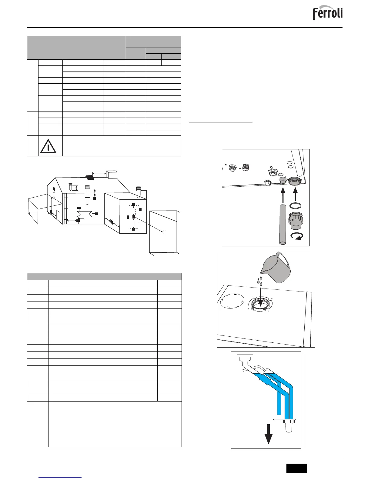
Table. 6 - Accessories
Position of terminals
fig. 17
Connection to multiple flues or single flues with natural draught
To connect the i25 / i29 boiler to a multiple flue or a single flue with natural draught, the
flue or chimney must be expressly designed by professionally qualified technical person-
nel in conformity with the current standards and regulations.
In particular, flues and chimneys must:
• Be sized according to the method of calculation given in the standard.
• Be tight with respect to the products of combustion, resistant to the fumes and heat
and impermeable to condensate.
• Have a circular or square cross-section (some hydraulically equivalent sections are
permissible), with a vertical progression and with no constrictions.
• Have the ducts conveying the hot fumes at a suitable distance or separately from
combustible materials.
• Be connected to just one unit per floor, for not more than 6 units (8 if there is a com-
pensation duct or opening).
• Have no mechanical suction devices in the main ducts.
• Be at low pressure, all along their length, in conditions of stationary operation.
• Have at their base a collection chamber for solid materials or condensate, of at least
0.5 m, equipped with an airtight metal door.
3.7 Condensate drain connection
Installation
The boiler has an internal trap for draining condensate. Fit the inspection coupling A and
the hose B. Fill the trap with approx. 0.5 L of water and connect the hose to the disposal
system.
fig. 18
Losses in m
eq
Air
inlet
Fume exhaust
Vertical Horizontal
Ø 80
PIPE
1 m M/F 1KWMA83W 1.0 1.6 2.0
BEND
45° M/F 1KWMA65W 1.2 1.8
90° M/F 1KWMA01W 1,5 2.0
PIPE SECTION
with test point 1KWMA70W 0.3 0.3
TERMINAL
air, wall 1KWMA85A 2.0 -
fumes, wall with antiwind 1KWMA86A - 5.0
FLUE
Split air/fumes 80/80 010027X0 - 12.0
Fume outlet only Ø80 010026X0 +
1KWMA86U
-4.0
Ø 60
PIPE
1 m M/F 1KWMA89W 6.0
BEND
90° M/F 1KWMA88W 4.5
REDUCTION
80/60 041050X0 5.0
TERMINAL
fumes, wall with antiwind 1KWMA90A 7.0
ATTENTION: CONSIDER THE HIGH PRESSURE LOSSES OF Ø60 ACCESSORIES;
USE THEM ONLY IF NECESSARY AND AT THE LAST FUME EXHAUST SECTION.
Minimum dimensions of fume exhaust terminals
A
Directly under an opening, air inlet, openable window, etc. 300 mm
B
Above an opening, air inlet, openable window, etc. 300 mm
C
Horizontally to an opening, air inlet, openable window, etc. 300 mm
D
Under gutters, drain pipes 75 mm
E
Under cornices or under eaves 200 mm
F
Under balconies or garages 200 mm
G
From a drain pipe or a vertical drain pipe 150 mm
H
From an internal or external corner 100 mm
I
Above ground level, a roof or balcony 300 mm
J
From a surface facing the terminal 600 mm
K
From a terminal facing the terminal 1200 mm
litres
From a garage opening (e.g. door, window) with access to the home 1200 mm
M
Vertically from a terminal on the same wall 1500 mm
No
Horizontally from a terminal on the same wall 300 mm
O
From the wall on which the terminal is fitted N/A
P
From a vertical structure on the roof 150 mm
Q
Above the intersection with the roof 300 mm
NOTES
•
N/A = Not applicable
• Also, the terminal must be at least 150 mm (in case of forced intake) from an opening made
in the structure of the building to house a fitted element such as a window frame.
• Positions of condensate drain terminals: if the fume exhaust is provided for at a low level,
the potential effect of the flue gas cloud must be considered. Special flue gas management
kits are available by request.
• The flue gas cloud must not be directed towards:
- A frequented approach
- A window or door
- An adjacent property