i25 / i29
5
EN
cod. 3541I730 - Rev. 02 - 11/2016
A
In areas characterised by the presence of hard water, treatment may be nec-
essary to prevent the formation of scale in the boiler.
A
Make sure to use the water treatment product in the correct concentration, in
compliance with the producer's instructions.
3.4 Gas connection
The gas must be connected to the relevant connection (see fig. 26) in conformity with the
current standards, using a rigid metal pipe or a continuous surface flexible s/steel tube
and installing a gas cock between the system and boiler. Make sure all the gas connec-
tions are tight.
3.5 Electrical connections
Important
B
The unit must be connected to an efficient earthing system in conformity with current safety
regulations. Have the efficiency and suitability of the earthing system checked by profession-
ally qualified personnel; the Manufacturer declines any liability for damage caused by failure
to earth the system.
The boiler is prewired and provided with a "Y" type cable (without plug) for connection to the
electric line. The connections to the power supply must be permanent and equipped with a
double-pole switch with contact opening distance of at least 3 mm, installing fuses of max. 3A
between the boiler and the line. Make sure to respect the polarities (LINE: brown wire / NEU-
TRAL: blue wire / EARTH: yellow/green wire) in connections to the electric line.
B
The unit's power cable must not be replaced by the user; if damaged, switch the unit off and
have the cable replaced by professionally qualified personnel. If replacing the power cable,
only use
"HAR H05 VV-F"
3x0.75 mm2 cable with max. ext. diameter of 8 mm.
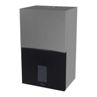
Room thermostat (optional)
B
IMPORTANT: THE ROOM THERMOSTAT MUST HAVE VOLTAGE-FREE CONTACTS.
CONNECTING 230 V TO THE ROOM THERMOSTAT TERMINALS WILL PERMANENTLY
DAMAGE THE ELECTRONIC BOARD.
When connecting time controls or a timer, do not take the power supply for these devices from
their breaking contacts Their power supply must be by means of direct connection from the
mains or with batteries, depending on the kind of device.
Accessing the electrical terminal block
The electrical terminal block can be accessed after removing the casing. The layout of the terminals for
the various connections is also given in the wiring diagram in
fig. 31
.
fig. 10 - Accessing the terminal block
3.6 Fume system
Important
This unit is a "C type" with sealed chamber and forced draught, with air inlet and flue
exhaust to be connected to one of the following flue systems. Before installation, with the
aid of the tables and calculation methods given, check that the pipes of the flue system
do not exceed the maximum permissible lengths. The current standards and local regu-
lations must be observed. It is absolutely essential, to ensure that products of combus-
tion discarging from the terminal cannot re-enter the building, or enter any adjacent
building, through ventilators, windows, doors, natural air infiltration or forced ventilation/
air conditioning.
B
Only a Ferroli flue system (with respective accessories) must be used with this
unit, as required by BS 5440 and CE standards.
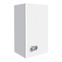
Baffles
Boiler operation requires fitting the baffles supplied with the unit, according to the following tables.
Before inserting the fume outlet pipe, it is therefore necessary to check there is the right diaphragm
(when it is to be used) and that it is correctly positioned. To replace the baffle (rif. 1 -
fig. 11
), proceed
as indicated in
fig. 11
.
fig. 11
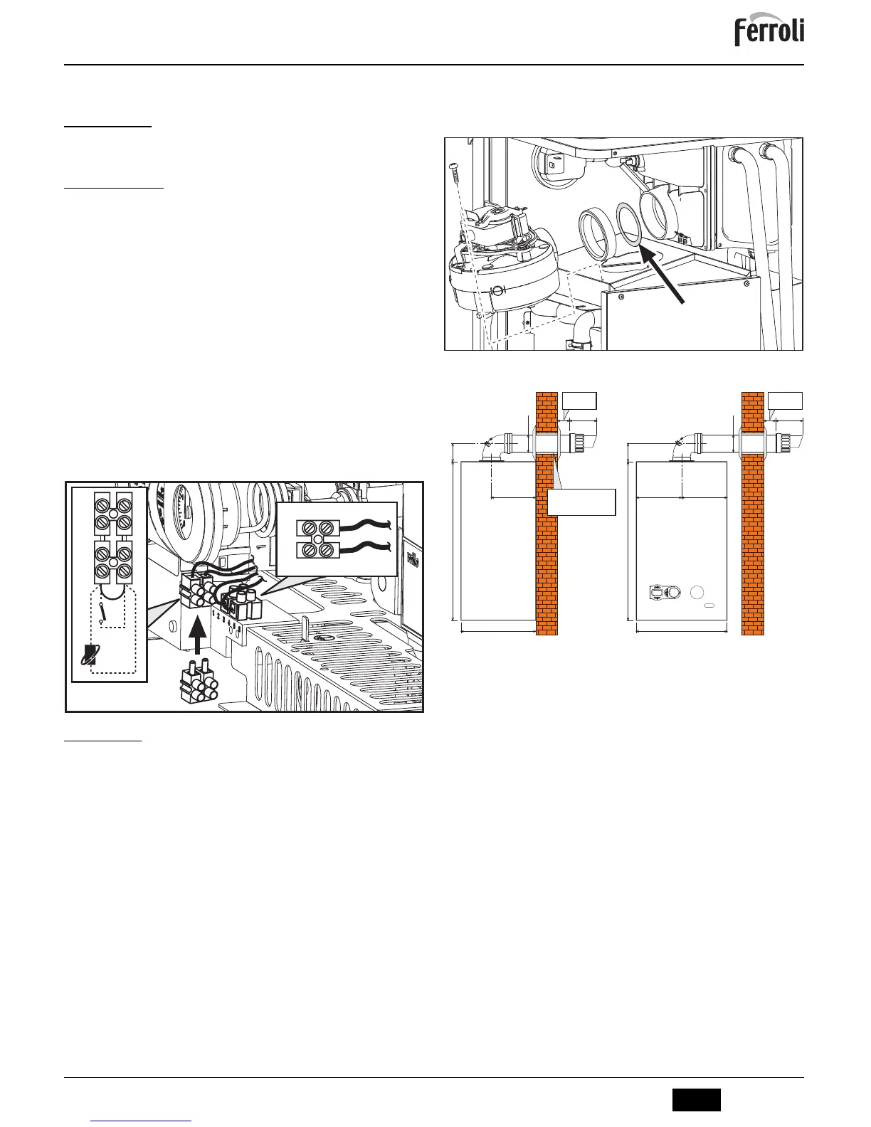
Standard coaxial installation
fig. 12 - Standard coaxial installation
Horizontal flue installation
1. Define the position for installing the unit.
2. If using standard flue this must be installed level. For extended horizontal flue
lengths over 1m a fall of 3° (55mm per meter) of the flue exhaust should be incor-
porated back to the boiler.
3. Make a hole of diameter 10 - 20 mm greater than the nominal diameter of the con-
centric pipe used.
4. If necessary, cut the terminal length to size, ensuring that the external pipe pro-
trudes from the wall by between 10 and 60 mm. Remove the cutting burrs.
5. Connect flue to the boiler, positioning the seals correctly. Seal the flue into the wall
with silicone or sand + cement and cover with wall seals provided.
A
Flue seals should be lubricated with a silicone type grease to prevent damage
(grease not supplied).