8
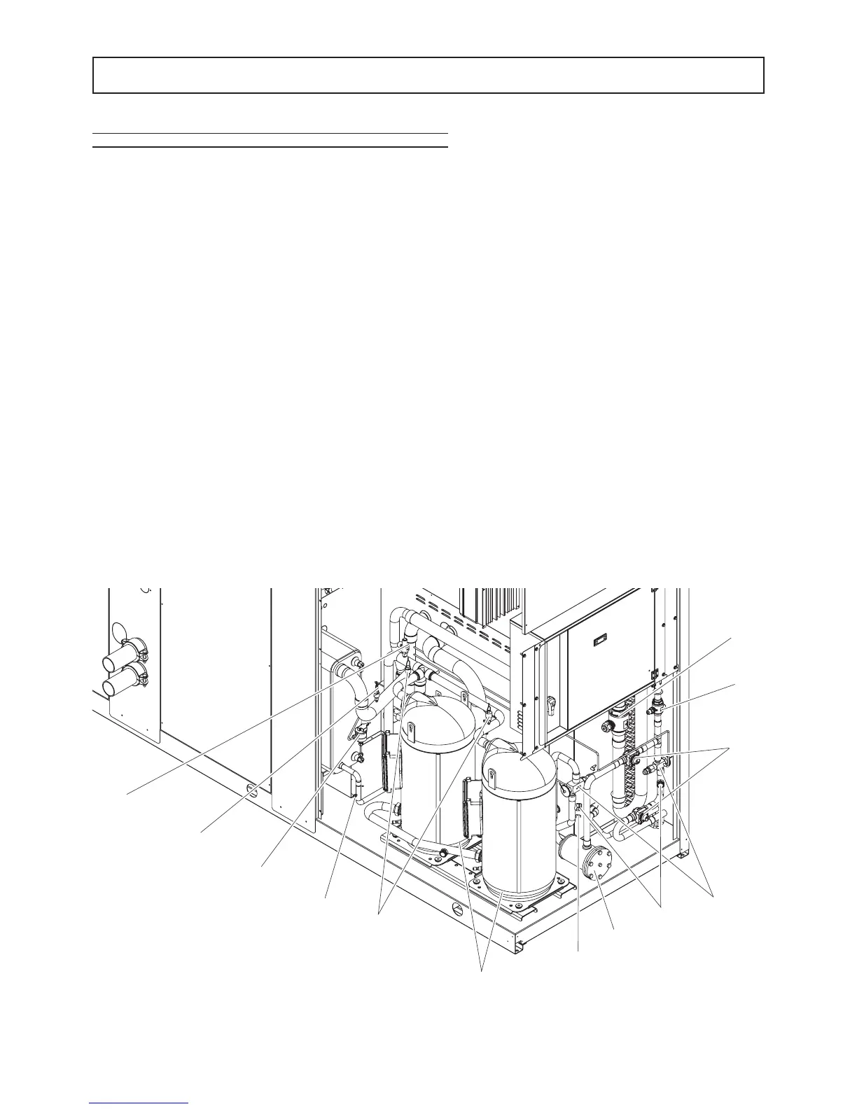
Hydraulic and cooling circuit components
10. Safety valve. Installed on the delivery pipe of the compressors, this operates if extreme faults should occur in the plant.
11. Fluid cock. Ball type, this allows the gas flow on the fluid line to be turned on and off. Along with the cock on the compres-
sor delivery, it allows the components of the fluid line to be subj
ected to extraordinary maintenance work and the compressors
to be replaced if necessary (without discharging the coolant from the unit).
12. Compressor delivery cock. Ball type, allows the gas delivered to the compressors to be turned on and off.
13. Dehydrator filter. Mechanical type. Retains impurities and traces of moisture in the circuit. Hermetic type for models 50÷80;
cartridge type for models 90÷200.
14. Fluid and humidity indicator. Signals when fluid passes through the circuit, indicating that the coolant charge is correct.
The fluid indicator light also indicates the amount of moisture in the coolant by changing colour.
15. Low pressure switch (N°1 of series IR version, N°2 of series IP version). With fixed setting. It is installed on the suction
pipe and blocks the compressors if the operating pressures drop below the tolerated values. Automatically resets as the pres-
sure increases. If it activates frequently, the unit will block and can
only be restarted by resetting via the user interface terminal.
16. High pressure switch (n°2). With fixed setting. Are is installed on the delivery pipe and blocks the compressors if the ope-
rating pressures exceed the tolerated values. If it activates, the unit will block and can only be restarted by resetting via the user
interface terminal.
17. Thermostatic valve. With external equalizer, this supplies the evaporator correctly, keeping the selected overheating degree
at a steady level.
18. Water differential pressure switch. This is standard supply and is installed on the connections between the water inlet and
outlet of the exchanger. It stops the uni
t if it activates.
19. Pressure taps: 1/4 " SAE (7/16" UNF) type with flow regulator. Allow the operating pressure of the system to be mea-
sured: compressor delivery, lamination component inlet, compressor intake.
20. Pressure taps: 5/16 " SAE type with flow regulator. Allow the charge/discharge of the gas from the system, precisely from
compressor outlet an expansion valve inlet.
21. Electrical heating elements to heat the compressor oil. "Belt" type. These activate when the compressor turns off and
keep the temperature of the oil sufficiently high so as to prevent coolant from migrating during these pauses.
Fluid receiver (IP unit only), this is a plenum tank that accounts for variations to the coolant charge the machine must supply
as the summer/winter operating mode varies.
Fluid separator (IP unit only), on the compressor intake to protect against possible fluid back-flows.
GENERAL SPECIFICATIONS
 Loading...