10
INSTALLATION
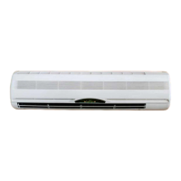
WALL UNIT INSTALLATIONS
AIR VENT
CONDENSATE DRAIN
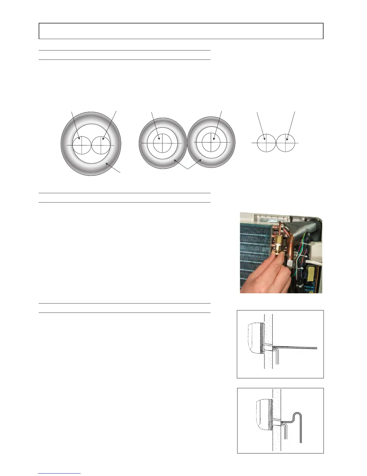
Fig 1
Fig 3
Fig 4
INGRESSO ACQUA
USCITA ACQUA
ISOLAMENTO
NO
INGRESSO ACQUA
USCITA ACQUA
ISOLAMENTO
SÌ
INGRESSO ACQUA
USCITA ACQUA
NO
1 The insulation must cover both water inlet and outlet pipes as shown
2 Use polyethylene insulation (minimum thickness 8mm)
1 Connect the water inlet and outlet pipes, turn the unit on and set it
to cool mode; make sure the valve opens
In this way water starts entering the coil
2 Check for water leaks along the hydraulic connections
If there are no leaks, open the air vent and air starts coming out of
the coil
Attention: During these operations, be careful not to touch live
electrical parts
3 Close the air vent
Carry out the condensate drain pipe connection, making sure nothing
can hinder the natural drainage of the condensate which forms in
cooling mode
Proceed as follows:
Ensure a minimum slope for the flow of condensate
Avoid any hindrances to the flow
After connecting, make sure the water flows properly out of the
machine
1 Connect the condensate drain pipe
2 Make sure the drain pipe does not have traps or curves that hinder
the flow of condensate
3 Check correct flow by pouring water into the tray and make sure it
comes out through the drain pipe installed
Fig 2
WATER INLET WATER INLET WATER INLETWATER OUTLET
INSULATION
INSULATION
WATER OUTLET WATER OUTLET