2.3 Foreseeable misuse of the STO function
The following are examples of foreseeable misuse and are not approved as
intended use:
– Bridging of the STO function.
–
Use in applications where switching off can result in hazardous movements or
conditions.
NOTICE
The STO function is not sufficient as the sole safety function for drives that are
subject to permanent torque or force (e.g. suspended loads, vertical axes).
Note
The STO function does not provide protection against electric shock, only against
dangerous movements!
2.4
Requirements for product use
–
Provide the complete product documentation to the following personnel:
– The design engineer and the installer of the machine or system.
– The personnel responsible for commissioning.
–
Keep this documentation safe throughout the entire product lifecycle.
– Ensure compliance with the specifications in this documentation. Also comply
with the documentation for the other components and modules (e.g. motor
controller, circuits, etc.).
– Observe all of the legal regulations applicable for the installation site and the
following documents:
– Regulations and standards.
–
Regulations of the testing organisations and insurers.
– National regulations.
For correct and safe use of the STO function:
–
Conduct a risk assessment for your machine.
– Comply with the specified safety characteristics
è
8 Technical data.
2.5 Product conformity
The motor controller with integrated STO safety function is a safety-related part of
the control systems. Certain configurations of the product have been certified by
Underwriters Laboratories Inc. (UL).
The product-relevant directives are listed in the declaration of conformity
è
www.festo.com/sp.
Product conformity
in accordance with EU EMC Directive
in accordance with EU Machinery Directive
in accordance with EU RoHS Directive
to UK EMC Regulations
to UK Supply of Machinery Regulations
to UK RoHS Regulations
Tab. 3:
Product conformity
2.6 Transport and storage conditions
– Protect the product during transport and storage from excessive stress factors,
such as:
– Mechanical loads.
– Temperatures that are too high or too low.
–
Moisture.
– Aggressive atmospheres.
–
Store and transport the product in its original packaging. The original pack-
aging offers sufficient protection from typical stresses.
2.7 Technical prerequisites
For correct and safe use of the product:
–
Carry out a risk assessment for your machine or system.
– Comply with the specified safety characteristics
è
8 Technical data.
–
Comply with the specified connection and ambient conditions for all connected
components
è
8 Technical data. Only compliance with the limit values and/or
load limits will enable operation of the product in accordance with the relevant
safety directives.
3
Product overview
3.1 Scope of delivery
Component Number
Motor controller CMMO-ST-C5-1-LKP 1
Documentation for the product:
– Brief documentation for the CMMO-ST + quick guide for positioning systems
(OMS)
– Special documentation corresponding to the certifications of the product
1
Assortment of plugs NEKM-C-14 with 6 connectors for control interface [X1], refer-
ence switch [X1A], safety function STO [X3], encoder [X2], motor [X6], power supply
[X9]
1
H-rail bracket, pre-assembled 1
Tab. 4:
Scope of delivery
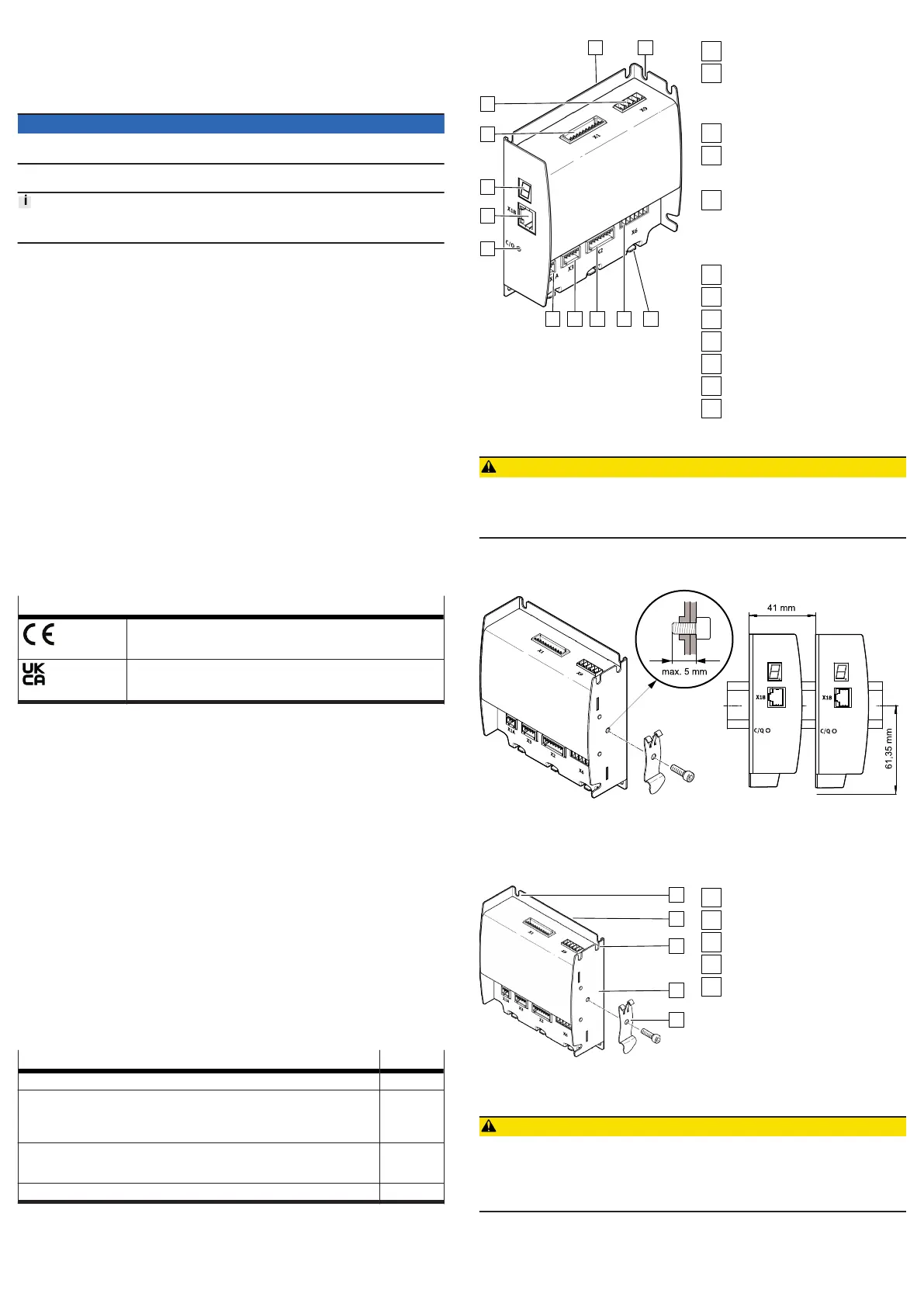
3.2 Product design
Fig. 1: Components of the CMMO-ST
[X9] Load/logic voltage
[X1] control interface to open-loop
control with PLC/IPC
– IO-Link/I-Port
– optional: digital I/Os
7-segment display
[X18] Ethernet (RJ-45)
– TCP/IP parameterisation interface
– Modbus TCP control interface
Link/activity LED C/Q
– LED green: communication OK
– LED red: communication error
– LED off: IO-Link/I-Port is not config-
ured as control interface
[X1A] reference switch
[X3] STO (Safe torque off)
[X2] encoder RS422
[X6] motor
FE functional earth (3x)
Mounting surface (H-rail)
Mounting surface
4
Mounting
CAUTION
Unexpected and unintended movement of the drive during mounting, installation
and maintenance work.
• Before starting work: switch off power supplies.
• Lock the power supplies to prevent accidental reactivation.
4.1 Mounting the motor controller
The controller can be mounted with an H-rail or on an even surface.
Fig. 2:
Mounting on an H-rail
Mount the CMMO-ST on the H-rail as follows:
1.
Attach the CMMO-ST to the H-rail from above with the hook of the H-rail clip.
2. Press down on the H-rail until the CMMO-ST clicks into place.
Mount the CMMO-ST on the side or rear mounting surface as follows:
Fig. 3:
Mounting on an even surface
Remove the H-rail bracket
Rear mounting surface
Notches (3x) for rear mounting
Side mounting surface
Recesses (4x) for side mounting
5
Electrical installation
CAUTION
Unexpected and unintended movement of the drive during mounting, installation
and maintenance work.
• Before starting work: switch off power supplies. Cancelling the enable signal on
the controller is not sufficient.
• Lock the power supplies to prevent accidental reactivation.

 Loading...