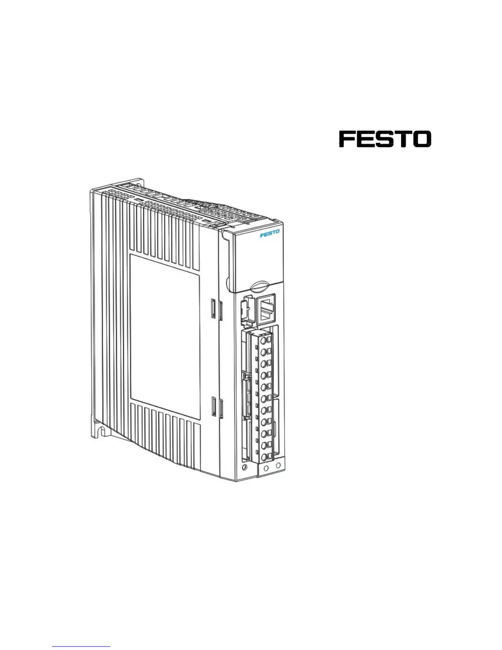
What to do if the Festo CMMB-AS-0x shows an Overcurrent error?
Manufacturer | Festo |
---|---|
PWM frequency | 20 kHz |
Resolution of the analogue value | 12 bit |
Sampling time | 1 ms |
Number of digital inputs | 4 |
Short circuit strength | Yes |
Protection class | IP20 |
Communication Interface | CANopen |
Category | Controller |
Operating voltage range DC | 18 - 30 V DC |
Nominal operating voltage DC | 24 V |
Nominal value range voltage | 0 ... 10 V |
Nominal value range current | 0 ... 20 mA |
Storage Temperature | -20 ... 70 °C |
General safety instructions for product use, including commissioning, repair, and de-commissioning.
Specifies conditions for product use, including transport, storage, and technical requirements.
Provides an overview of the CMMB motor controller series and associated servo motors and cables.
Presents a detailed view of the CMMB motor controller with dimensions and connector labels.
Details mechanical installation requirements, including environmental conditions and mounting.
Covers electrical installation aspects, including front panel view and connector details.
Explains the overall wiring of the CMMB servo system, including safety warnings.
Describes the functions of the LED display and buttons for controller setup and navigation.
Illustrates the menu structure and navigation flow for setting controller parameters via the panel.
Explains the Easy Use function for quick controller setup and auto-tuning for optimal performance.
Guides on starting with the CMMB Configurator software, including language and project file management.
Details the procedure for initializing, saving, and rebooting controller parameters within the software.
Explains how to update the motor controller's firmware using the CMMB Configurator software.
Describes how to read and write controller configurations, useful for batch production setups.
Covers the configuration of digital inputs and outputs for the CMMB motor controller.
Outlines the initial steps for starting a control mode, including wiring and I/O configuration.
Details the velocity control modes, specifying how target speed is set via analog or digital inputs.
Explains torque control modes, including analog torque mode for motor torque regulation.
Describes position mode for rotating the motor to absolute or relative positions, including position table mode.
Covers pulse train mode where target velocity is specified via pulse input and gear ratio.
Explains homing mode for establishing a consistent home position upon power-up.
Describes the auto-tuning function to stimulate the system and set stiffness based on inertia ratio.
Details manual tuning process for applications not supported by auto-tuning, adjusting loop gain and filters.
Discusses factors affecting tuning results, including control command smoothness and machine design.
Lists alarm codes from Error_State1, their reasons, and troubleshooting steps.
Lists extended alarm codes from Error_State2 with reasons and troubleshooting guidance.
Details parameters accessible via the LED display's monitor mode, including firmware version and status.
Lists parameters related to control loop settings, such as velocity loop bandwidth and notch filter frequency.
Covers parameters for configuring analog and digital I/O functions and operation modes.
Details motor-related parameters, including motor code, encoder type, and inductance.
Lists miscellaneous controller parameters like Node ID, baud rate, and brake resistor settings.
Explains RS232 wiring for communication, covering point-to-point and multi-point connections.
Describes the master/slave protocol for RS232 communication, including default settings.
Details the RS232 data protocol, compatible with CANopen SDO, for accessing parameters.
Provides examples of RS232 telegrams for setting control words and operation modes.