35
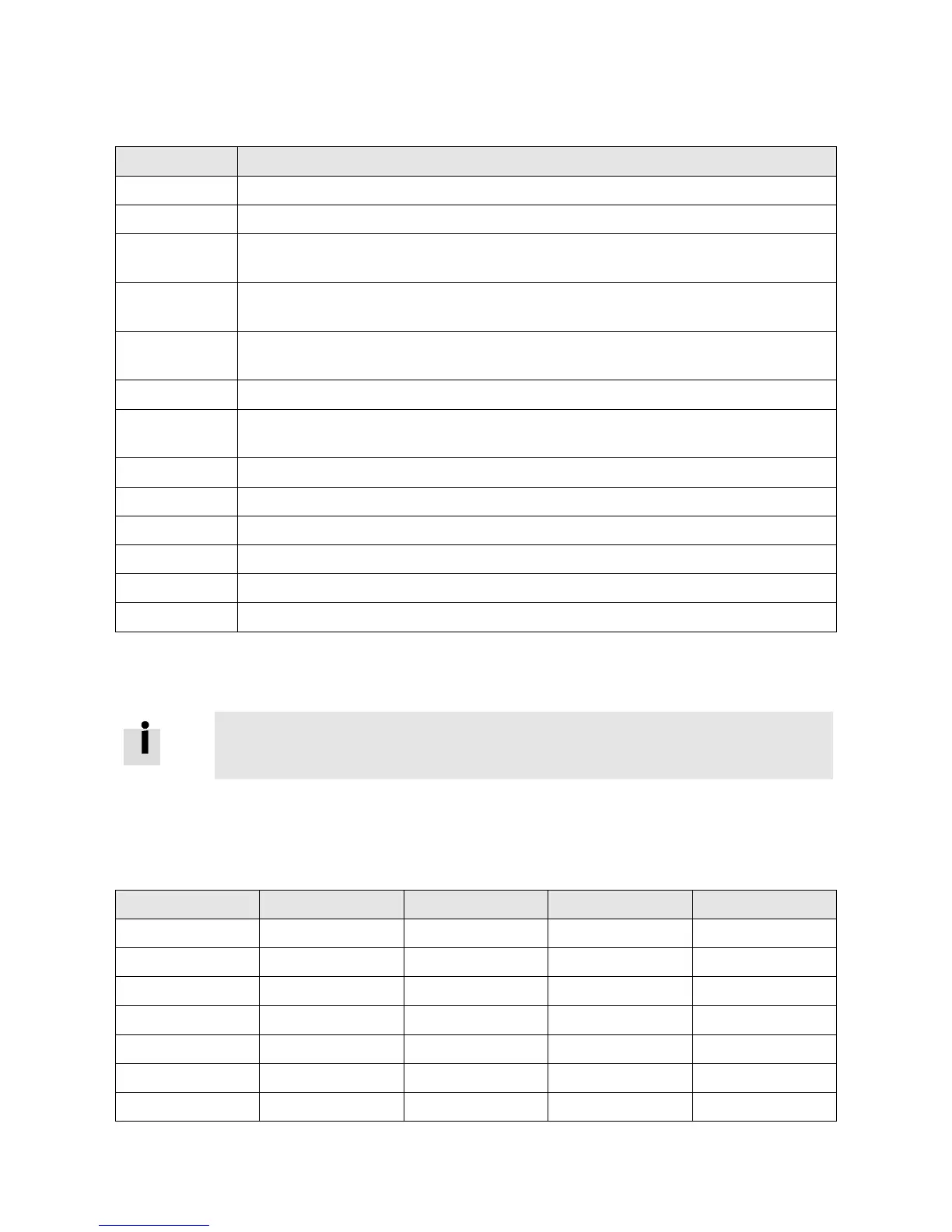
The following table lists the digital output functions:
Table 5-3: Digital output functions
Controller is ready to be enabled
Under position mode, position difference between Pos_Actual and
Pos_Target<Target_Pos_Window(6067.00),duration>=Position_Window_time(6068.00)
|Speed_1ms(60F9.1A)|<=Zero_Speed_Window(2010.18) and
duration >=Zero_Speed_Time(60F9.14)
Signal for controlling the motor brake. By this signal an external relay can be controlled, by which
the motor brake is controlled. (see chapter 3.2.4).
|Speed_Error(60F9.1C)|<Target_Speed_Window(60F9.0A)
Encoder position is inside a range around the index position. This range is defined by
Index_Window(2030.00).
In torque mode actual speed reached Max_Speed(607F.00)
Position limit function is active
Position table mode running
5.5.3 Gear ratio switch (expert only)
Information
This function is recommended for experienced users only.
There are 8 groups of gear ratio parameters which can be selected via the digital inputs. Gear ratio is only
used for pulse train mode (see chapter 6.5).
Table 5-4: Gear ratio switch
 Loading...


