65
Chapter 7 Tuning of the servo system control
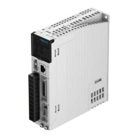
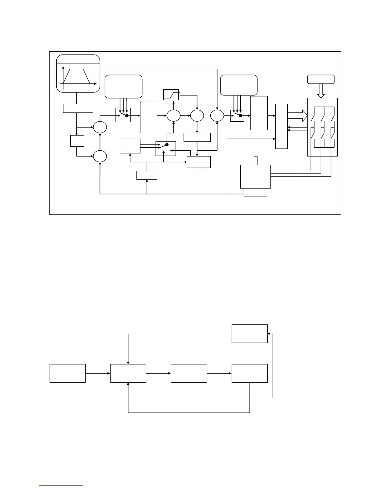
Figure 7-1: Servo system control block diagram
Figure 7.1 shows the servo system control block diagram. It can be seen from the figure that the servo
system generally includes three control loops: current loop, velocity loop and position loop.
The adjustment process of a servo system is used to set loop gain and filters to match the mechanical
characteristics, and finally to prevent the entire system from oscillating, to permit it to follow commands
quickly and to eliminate abnormal noise.
7.1 Auto-tuning
The auto-tuning function will try to stimulate the motor and load system by some motions, and get the
inertia of the load. If auto-tuning is successful, stiffness will be auto-set according to the inertia ratio.
 Loading...


