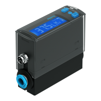
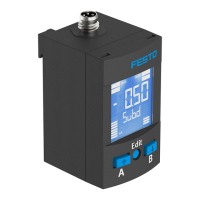
The monitored pressure values record either the relative pressure or the differen
tial pressure (SDE5...Z...).
SDE5 with switching output: when the switching point is reached, the pressure
sensor closes or opens a circuit.
The SDE5 is available with different switch/teach functions . The switching func
tion is preset ex works and can only be changed for the SDE5...FP... .
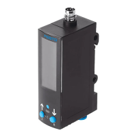
5 Mounting
5.1 Mount SDE5 with wall bracket
NOTICE!
Accumulation of condensate in the product can impair its functionality.
• Install the product in such a way that condensate from the compressed air
lines cannot collect in the product.
Mounting several wall brackets
1
Dovetail
2
Strap
Fig. 3 Connection of wall bracket
1. Push the dovetail of the wall bracket into the connecting groove of the next
wall bracket (push away the strap).
2.
Fasten first and last wall bracket with 2screws each (Æ 4mm).
If more than 3 wall holders are being used: mount every second wall holder
with 2screws each.
1
4 snapin detents
2
Strap
Fig. 4 Mount SDE5 on wall bracket
3. Press SDE5 into the wall bracket.
Ä
4 snap latches engage audibly.
Individual mounting
• To make it easier to see the LED light, break out the strap of the wall bracket
when mounting individually.
6 Installation
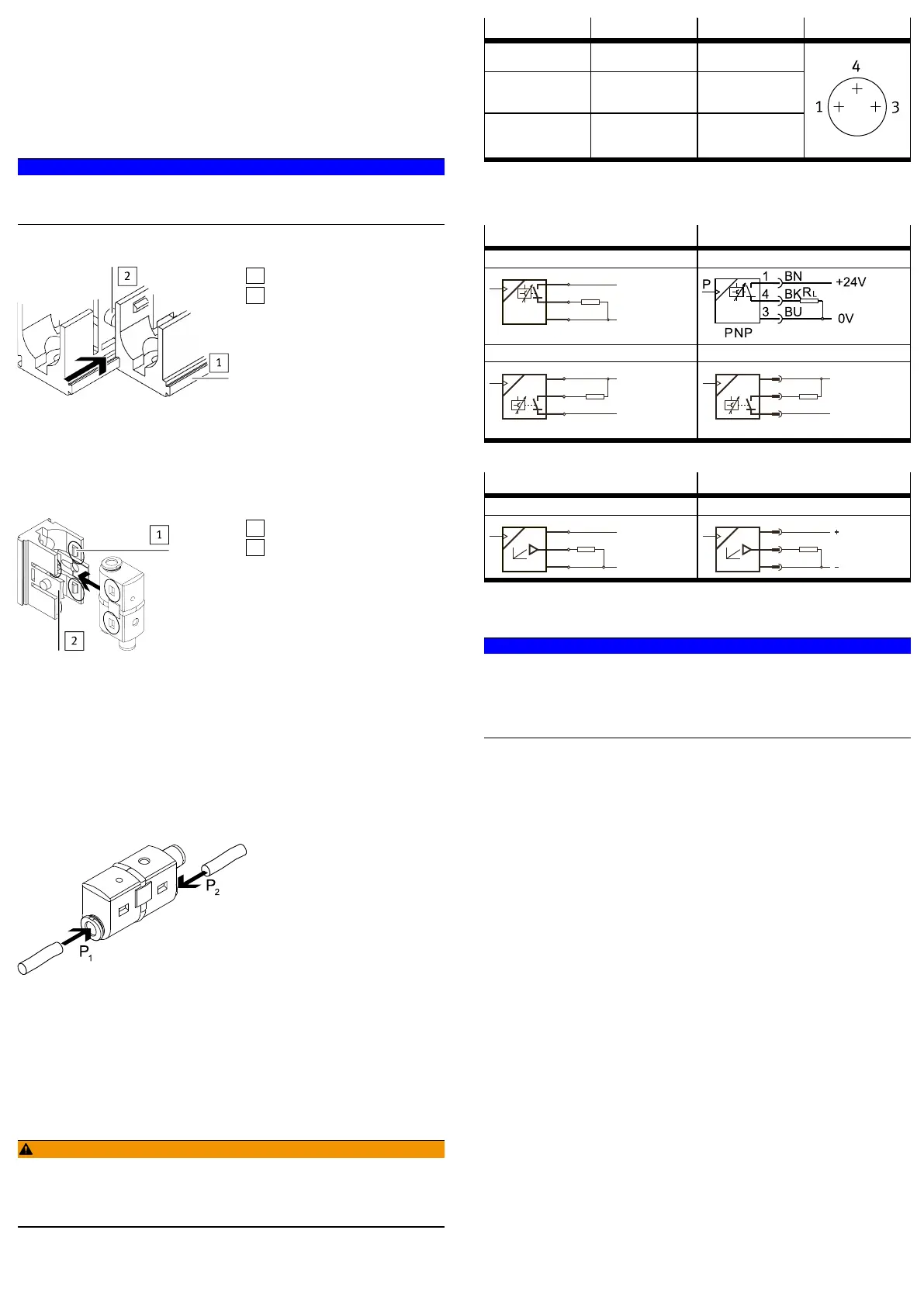
6.1 Pneumatic installation
Push-in connector
Fig. 5 Pushin connector
Push-in connector at one end
• Mount the hose to connection 1.
Push-in connector at both ends
1. Check pressure conditions.
With the pressure sensor for differential pressure (SDE5...Z...), the higher
pressure must be applied to port 1 (differential pressure = p1 p2).
2. Mount the hoses to connection 1 and 2.
6.2 Electrical installation
WARNING!
Risk of injury due to electric shock.
• For the electric power supply, use only PELV circuits that ensure a reliable
electric disconnection from the mains network.
• Observe IEC602041/EN602041.
1. Use signal lines that are shorter than 30m.
2. Configure binary outputs according to the wiring è Tab. 4 Pin allocation.
– Tightening torque for the union nut at the plug connector: max. 0.3Nm
Pin Wire colour
1)
Allocation Plug
1 Brown (BN) Operating voltage
+24VDC
4 Black (BK) Switching output A
(Out A) or analogue
output
3 Blue (BU) 0V
M8, 3pin
1) When using the connecting cable as per Accessories.
Tab. 4 Pin allocation
Circuit diagrams
Cable connection Plug connection
SDE5...P...K SDE5...P...M8
SDE5...N...K SDE5...N...M8
Tab. 5 Circuit diagrams for switching output
Cable connection Plug connection
SDE5...V...K SDE5...V...M8
Tab. 6 Circuit diagrams analogue output
7 Commissioning
NOTICE!
Voltage interruption during the storage process will make the product unusable.
After teaching, the values are written to the internal memory. If the save process
is aborted due to power interruption, the transfer process to the memory cannot
be completely carried out and the device becomes unusable.
• Ensure power supply for at least 10seconds after teaching.
è Fig.6 shows an overview of the possible settings and displays. The activities
are described in the subsequent sections.
 Loading...