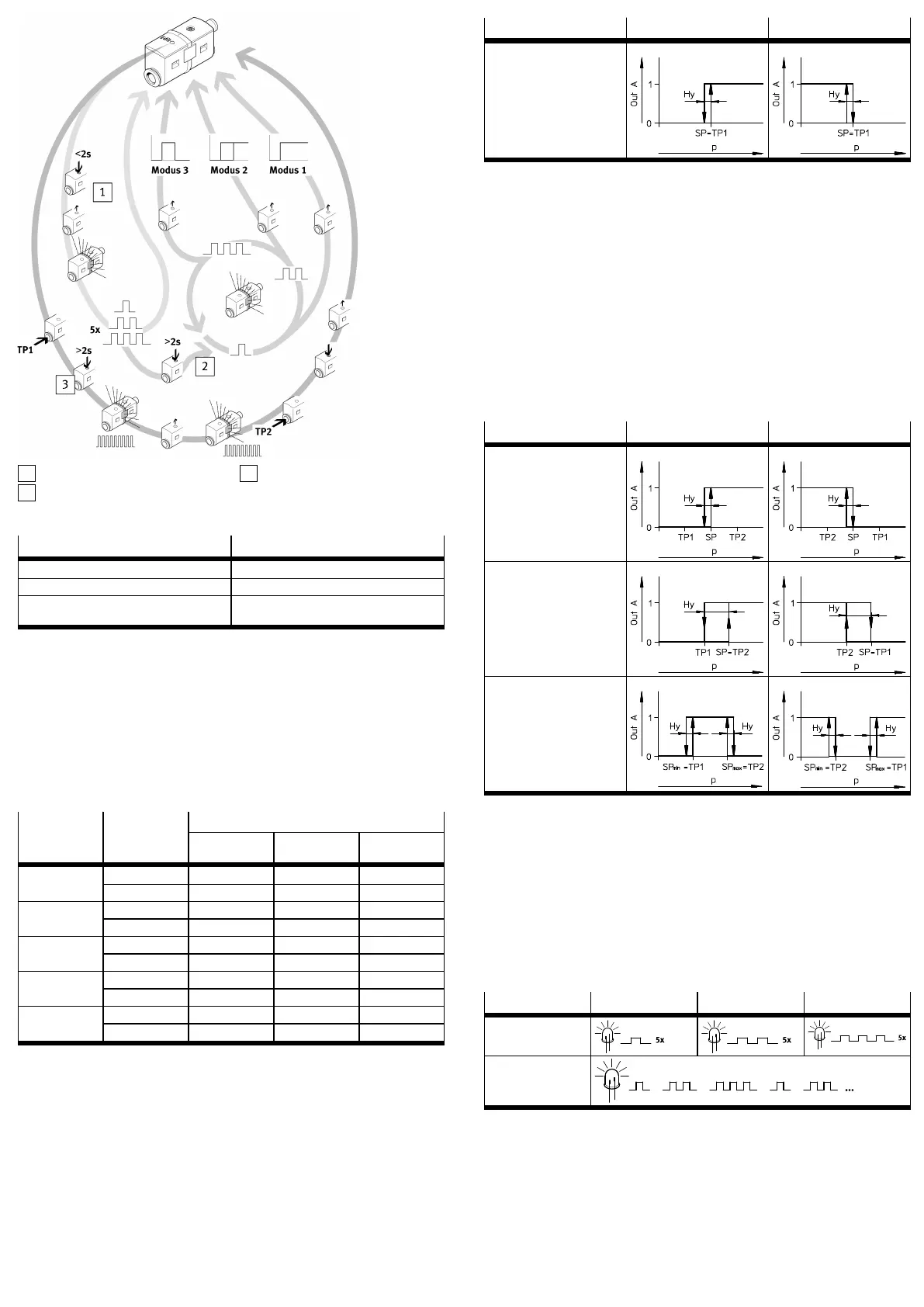
1
Mode display
2
Mode selection
3
Switching pressure setting
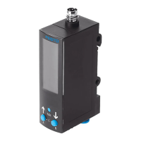
Fig. 6 Commissioning
Legend item Description
Mode display Display of the set mode (only with ...FP)
Mode selection Selection of modes 1 to 3 (only with ...FP)
Switching pressure setting Teaching the switching pressures TP1 and TP2
(mode 0…3)
Tab. 7 Legend Commissioning variants
7.1 SDE5-...-X without Edit button
The SDE5...X without Edit button is preset ex works with fixed switching points
and requires no additional commissioning.
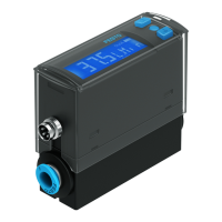
7.2 SDE5-...-NF-...-V with analogue output
1. Switch on the operating voltage.
Ä
LED lights green.
2. Apply switching pressure to SDE5.
Ä
The pressure measuring range is applied
è Tab. 8 Analogue signal dependent on pressure measuring rangeto the
analogue output as an electrical pressure proportional signal.
Signal rangeSensor Pressure
measuring
range
0V 5V 10V
bar 0 –0.5 –1SDE5V1
MPa 0 –0.05 –0.1
bar –1 0 1SDE5B2
MPa –0.1 0 0.1
bar 0 1 2SDE5D2
MPa 0 0.1 0.2
bar 0 3 6SDE5D6
MPa 0 0.3 0.6
bar 0 5 10SDE5D10
MPa 0 0.5 1
Tab. 8 Analogue signal dependent on pressure measuring range
7.3 SDE5-...-O/C-...-P/N with switching output
Set the switching pressure SP with one teach pressure
1. Switch on the operating voltage.
2. Apply teach pressure to SDE5.
3. Press and hold the Edit button for at least 2seconds.
Ä
LED flashes.
4. Release the Edit button.
Ä
Teach pressure is stored as switching point SP.
5. Ensure power supply for at least 10seconds.
6. Test in test run whether SDE5 switches as desired. The LED lights when the
switching signal is output.
Mode NO (normally open) NC (normally closed)
Mode 0:
Threshold value comparator
(threshold value with fixed hys
teresis Hy)
SDE5...O SDE5...C
Tab. 9 Signal curve over the applied pressure p with switching points
7.4 SDE5-...-O1/O2/O3/C1/C2/C3-...-P/N with switching output
Set the switching pressure SP with two teach pressures TP1/TP2
1. Switch on the operating voltage.
2. Apply teach pressure TP1 to SDE5.
3. Press and hold the Edit button for at least 2seconds.
Ä
LED flashes.
4. Release the Edit button.
Ä
Teach pressure TP1 is stored.
5. Apply teach pressure TP2 to SDE5.
6. Press the Edit button until the LED stops flashing.
7. Release the Edit button.
Ä
Teach point TP2 is stored.
8. Ensure power supply for at least 10seconds.
9. Test in test run whether SDE5 switches as desired. The LED lights when the
switching signal is output.
Mode NO (normally open)
1)
NC (normally closed)
2)
Mode 1:
– Threshold value comparat
or (threshold value with
fixed hysteresis Hy)
– Switching pressure SP =
(TP1 ½+ TP2)
– Preset mode for output
function FP
SDE5...O1 SDE5...C1
Mode 2:
Hysteresis comparator
(threshold value with variable
hysteresis Hy)
SDE5...O2 SDE5...C2
Mode 3:
Window comparator with fixed
hysteresis Hy
SDE5...O3 SDE5...C3
1) Default settings: TP1 = 20% FS; TP2 = 80% FS
2) Default settings: TP1 = 80% FS; TP2 = 20% FS
Tab. 10 Signal curve over the applied pressure p with switching points
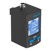
7.5 SDE5-...-FP-...-P/N with switching output
Set mode
1. Switch on the operating voltage.
2. Briefly press Edit button (< 2 seconds).
Ä
LED shows the current modeè Tab. 11 Mode display.
3. Press and hold the Edit button until the desired mode is displayed.
4. To save the mode, release the Edit button.
5. Ensure power supply for at least 10seconds.
6. Set switching pressure SP.
Mode 1 Mode 2 Mode 3
LED flash sequence for
set mode
1)
LED flash sequence at
change of mode
1) The currently set mode is displayed 5 times in succession. The SDE5 then switches to RUN mode.
Tab. 11 Mode display
Set the switching pressure with two teach pressures TP1/TP2
– Relationship between teach pressure, switching pressure and hysteresis
è Tab. 10 Signal curve over the applied pressure p with switching points.
1. When setting the switching points, note the following relationship between
the teach points:
– TP1 < TP2: programming as N/O contact
– TP1 (TP2 >+ 2% FS): Programming as N/C contact
2. Apply teach pressure TP1 to SDE5.
 Loading...