3. Press and hold the Edit button for at least 2seconds.
Ä
LED flashes.
4. Release the Edit button.
Ä
Teach pressure TP1 is stored.
5. Apply teach pressure TP2 to SDE5.
6. Press the Edit button until the LED stops flashing.
7. Release the Edit button.
Ä
Teach pressure TP2 is stored.
8. Ensure power supply for at least 10seconds.
9. Test in test run whether SDE5 switches as desired. The LED lights when the
switching signal is output.
8 Operation and use
NOTICE!
Property damage due to high temperatures.
Extreme pneumatic conditions (high cycle rate with high pressure amplitude) can
heat the product above 80C.
• Select the operating conditions (in particular the ambient temperature, pres
sure amplitude, cycle rate, current consumption) such that the product does
not heat up above 80°C.
• Switch on the operating voltage.
Ä
The SDE5 is in RUN mode (basic status).
9 Service
1. Turn off energy source and compressed air.
2. Clean sensor with nonabrasive cleaning agents.
10 Fault clearance
Fault description Cause Remedy
Pressure p < switching pressure
(SP)
regular operating status
è 4.1.2 LED display
No operating voltage or imper
missible operating voltage
Switch on the operating
voltage. / maintain operating
voltage range.
Connections are reversed
(reverse polarity)
Wire the SDE5 in accordance
with the pin allocation
è Tab. 4 Pin allocation.
Pressure failure Eliminate pressure failure.
No LED indicator
SDE5 defective Replace device.
Short circuit or overload at the
output
Rectify short circuit/overload.
Incorrect switching point taught Repeat teach procedure.
LED indicator or switching out
put does not react in accord
ance with the settings
SDE5 defective Replace device.
Tab. 12
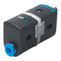
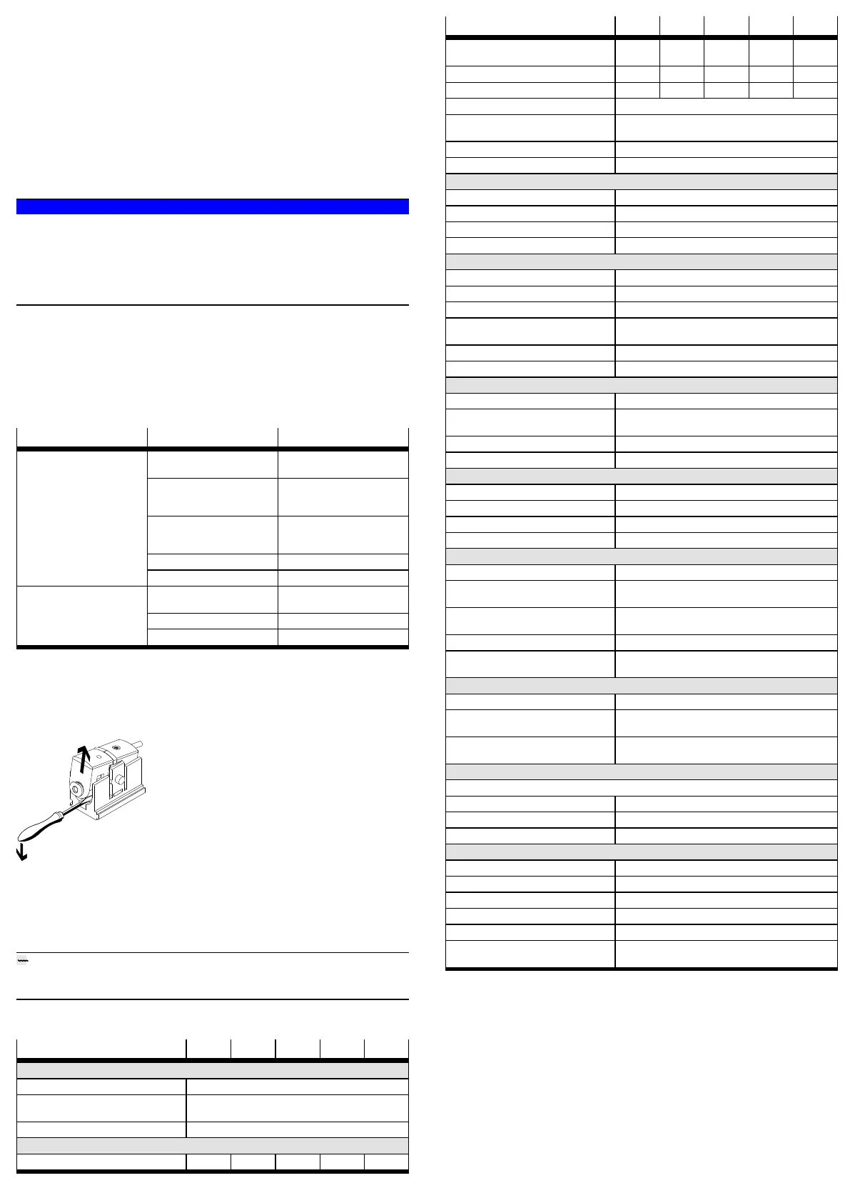
11 Disassembly
1. Turn off energy source and compressed air.
2. Disconnect pneumatic and electrical connections.
Fig. 7 Disassembly
3. Slide the screwdriver into the groove of the wall bracket and swivel out the
SDE5.
12 Disposal
ENVIRONMENT!
Send the packaging and product for environmentally sound recycling in accord
ance with the current regulations èwww.festo.com/sp.
13 Technical data
SDE5 -V1 -B2 -D2 -D6 -D10
General
Approval RCM, c UL us – Recognised (OL)
CE marking (declaration of conformity
èwww.festo.com/sp)
In accordance with EU EMC Directive
In accordance with EU RoHS directive
Note on materials RoHScompliant
Input signal/measuring element
Pressure measuring range [bar] 0…–1 –1…1 0…2 0…6 0…10
SDE5 -V1 -B2 -D2 -D6 -D10
Pressure measuring range [MPa] 0…–0.1 –0.1…
0.1
0…0.2 0…0.6 0…1
Max. overload pressure [bar] 5 5 6 15 15
Max. overload pressure [MPa] 0.5 0.5 0.6 1.5 1.5
Operating medium Compressed air to ISO85731:2010 [7:4:4]
Note on the operating medi
um
Lubricated operation possible
Temperature of medium [°C] 0…+50
Ambient temperature [°C] 0…+50
Output, general
Repetition accuracy [% FS] ±0.3 (momentary)
Temperature coefficient [% FS/K] max. ±0.05
Short circuit current rating Yes
Overload protection Present
Switching output
Accuracy [% FS] Max. ±0.5
Switching time (On/Off)
1)
[ms] 2 (typical) / 4 (max.)
Max. output current [mA] 100
Capacitive load (maximum
DC)
[nF] 100
Voltage drop [V] Max. 1.8
Inductive protective circuit adapted to MZ, MY, ME coils
Analogue output
Output characteristic [V] 0…10
Accuracy [% FS] ±3 (room temperature: 20…25°C)
max. ±4 (0…50°C)
Rise time [ms] 5 (typical) with resistive load
Min. load resistance [kΩ] 2
Electronics
Operating voltage range [VDC] 15…30
Noload supply current [mA] Max. 34
Readystate delay [ms] ≤20
Reverse polarity protection For all electrical connections
Electromechanics
Max. cable length [m] 30
Information on materials
cable sheath
PUR
Information on materials –
plug housing
Brass (nickelplated, chromeplated)
Cable diameter [mm] 2.9
Nominal conductor cross sec
tion
[mm"] 0.14
Mechanics
Mounting position Any, preferably vertical
2)
Information on materials
housing/keypad
Polyamide (POM) reinforced
Information on materials –
plug housing
PA
Display/operation
Threshold value setting range:
Switching pressure [% FS] 0…100 (recommended working range: 1…99)
Hysteresis (mode 2) [% FS] 0…100 (recommended working range: 1…99)
Hysteresis (mode 0, 1, 3) [% FS] 2 (permanently set)
Immission/emission
Storage temperature [°C] –20…+80
Degree of protection IP40
Protection class III
Shock resistance 30g acceleration with 11ms duration (halfsine)
Vibration resistance 0.35mm travel, 5g acceleration at 10…150Hz
Corrosion resistance class
CRC
2
1) Switching times are not applicable with activated additional function …TF (filter function).
2) Condensation must not collect in the pressure measuring cell.
Tab. 13 Technical data
 Loading...