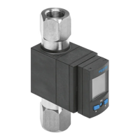
SOPA
Air gap sensor
Festo SE & Co. KG
Ruiter Straße 82
73734 Esslingen
Deutschland
+49 711 347-0
www.festo.com
Operating instructions
8163013
2021-08d
[8163015]
Translation of the original instructions
© 2021 all rights reserved to Festo SE & Co. KG
1
About this document
1.1 Purpose of the document
This document describes the use of the above-mentioned product. Certain
aspects of use are described in other documents and must be observed
è
1.2
Applicable documents.
1.2 Applicable documents
All available documents for the product
è
www.festo.com/sp.
Document Table of contents
Description of air gap sensor SOPA Functional description, installation, commis-
sioning, servicing, description of the IO-Link
parameters, technical data
Tab. 1:
Applicable documents
2 Safety
2.1 General safety instructions
– Only use the product in its original condition without unauthorised modifica-
tions.
– Only use the product if it is in perfect technical condition.
–
Only use media in accordance with the specifications è Technical data.
– Observe labelling on the product.
– Note that changes to the switching status (EDIT mode) become effective imme-
diately.
2.2
Intended Use
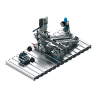
The air gap sensor SOPA is intended for distance monitoring in a range of
20 … 200 µm. The distance measurement is performed using a non-contact pneu-
matic measuring process. This enables it to be used in harsh ambient conditions.
2.3 Training of qualified personnel
Work on the product may only be carried out by qualified personnel who can
evaluate the work and detect dangers. The qualified personnel have skills and
experience in dealing with electrical (open-loop) control technology.
2.4 UL/CSA certification
In combination with the UL inspection mark on the product, the information in this
section must also be observed in order to comply with the certification conditions
of Underwriters Laboratories Inc. (UL) for USA and Canada.
UL/CSA certification information
Product category code NRNT2/NRNT8
File number E253738
Considered standards UL 508
CSA22.2 No. 14
UL mark
Tab. 2:
UL/CSA certification information
This device is intended to be used with a Class 2 power source or Class 2 trans-
former in accordance with UL1310 or UL1585.
As an alternative a LV/C (Limited Voltage/Current) power source with one of the
following properties can be used:
–
This device shall be used with a suitable isolating source such that the max-
imum open circuit voltage potential available to the product is not more than
30 V DC and the current is limited to a value not exceeding 8 amperes meas-
ured after 1 minute of operation.
–
This device shall be used with a suitable isolating source in conjunction with
a fuse in accordance with UL248. The fuse shall be rated max. 3.3 A and
be installed in the 30 V DC power supply to the device in order to limit the
available current.
3 Additional information
–
Contact the regional Festo contact if you have technical problems
è
www.festo.com.
– Accessories and spare parts
è
www.festo.com/catalogue.
– Device description file IODD
è
www.festo.com/sp.
4
Product overview
4.1
Structure
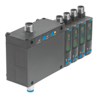
4.1.1 Product design
1
2 3 4
5
6
7
8
9
10
11
121314
13
3
15
16
17
18
19 20
Fig. 1: Product design
1
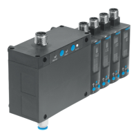
Supply port for supply pressure
2
Sensor module (max. 4 modules
permitted in combination with
control module)
3
Plug for electrical connection
4
Display
5
Edit button
6
B pushbutton
7
A pushbutton
8
Label holder
9
Pneumatic port for measuring
nozzle (outlet)
10
Supply port for operating pres-
sure
11
Vent screw (width across flats 14)
12
Mounting slides
13
Threaded sleeve (M4)
14
Blanking plug (M7)
15
Control module (optional)
16
Manual LED (green) – ready
indication for manual override
(SOPA-C..-H only)
17
Clean pushbutton (blow-out air)
(SOPA-C..-H only)
18
Status LED (yellow) – clean (blow-
out air)
19
Sense pushbutton (measuring air)
(SOPA-C..-H only)
20
Status LED (yellow) – sense
(measuring air)
4.1.2
Display components
Fig. 2:
LCD display
Display of binary output OutA
Display of binary output OutB
Display of binary output OutC
4-digit alphanumeric display
Toolbar for functions
Bar graph