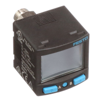
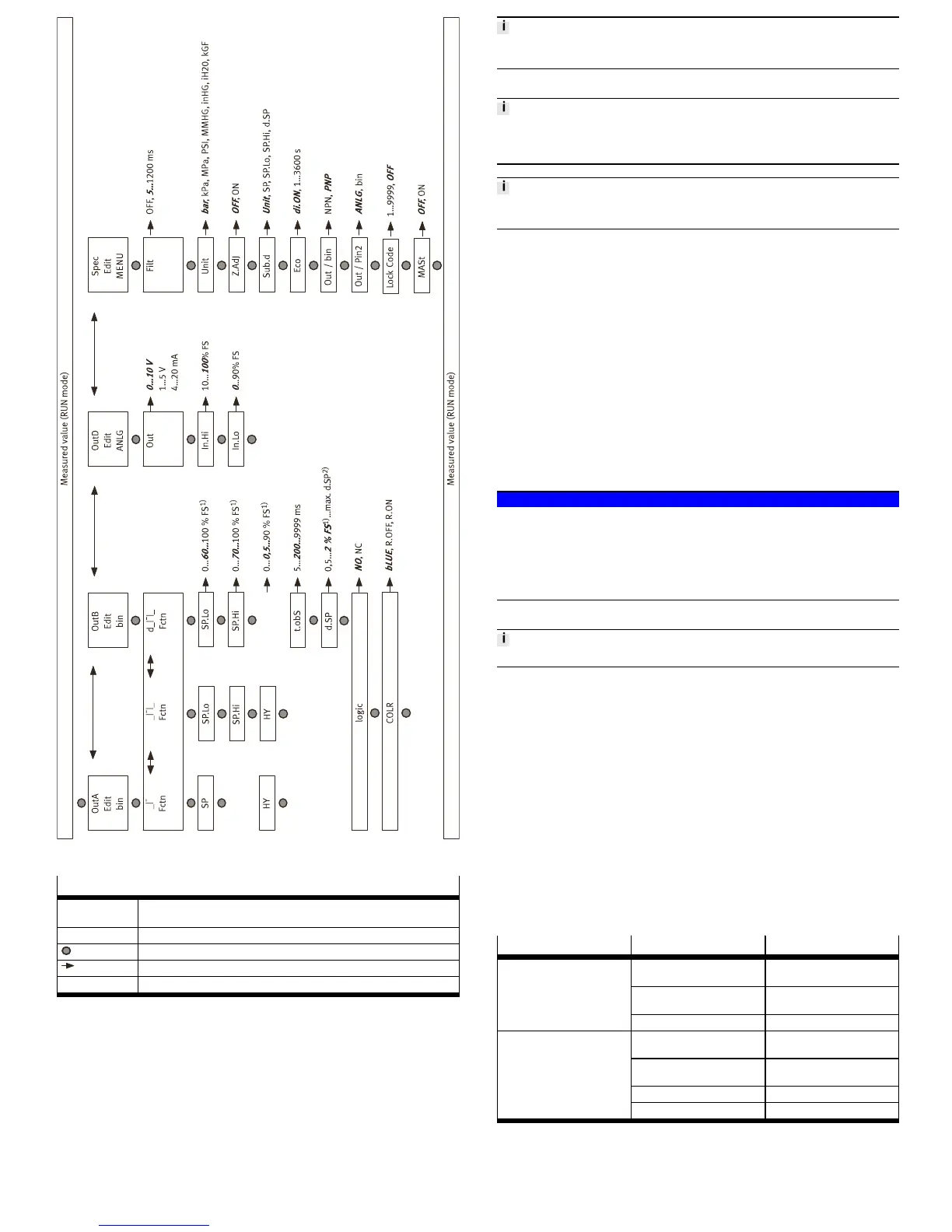
Fig. 7
Legend for è Fig.7
1)
The values refer to the respective measuring range. The display takes place in
the selected unit.
2)
The maximum value depends on SP.Lo and SP.Hi.
Edit button
A or B pushbutton
Bold, cursive Factory setting
Tab. 12
8.10 Zero point synchronisation (zero adjust)
Requirement:
– The sensor is ready for operation (RUN mode).
– [Z.AdJ] [ON] is set è 8.7 Change device settings (EDIT mode).
– The measured value lies in the range 0 bar ± 3 % FS.
1. Press the A pushbutton and B pushbutton simultaneously.
2. Press the EDIT pushbutton also.
Ä
[OK] appears. The zero point synchronisation was successful.
If [FAIL] appears: the zero point synchronisation was not successful. Check
requirements.
If [Z.AdJ] [OFF] is set for a later time, the device takes over the factory setting calib-
ration values.
8.11 Teach switching points (TEACH mode)
The process for teaching the switching outputs for OutA (A pushbutton) and OutB
(B pushbutton) is the same. In the following, the process is described using the
switching output OutA.
There is no timeout in the TEACH mode. The sensor changes to the RUN mode
only after the entire teach process is ended.
Requirement: The sensor is ready for operation (RUN mode).
If the security code is activated, the parameter entry option is blocked: [Lock]
flashes.
• Entering the security code è 8.4 Entering the security code
1. Establish switching function in the EDIT mode
è 8.5 Configuring switching output (EDIT mode)
2. Create pressure value 1.
3. Press the A pushbutton and Edit button.
Ä
– The current pressure value will then be adopted as the first teaching
point (TP1).
– [t-IN] flashes.
4. Create pressure value 2
5. Press the A pushbutton and Edit button.
Ä
– The current pressure value is adopted as the second teaching point
(TP2).
– Switch to the RUN mode.
9 Operation
NOTICE!
Property damage due to high temperatures.
Extreme pneumatic conditions (high cycle rate with large pressure amplitude) can
heat the product above 80°C.
• Select the operating conditions (in particular the ambient temperature, pres-
sure amplitude, cycle rate, current consumption) such that the product does
not heat up above the maximum permitted operating temperature.
9.1 Restoring factory settings (restore)
By restoring the factory settings, the current settings are lost.
1. Switch off operating voltage.
2. Keep the A and B pushbuttons pressed down simultaneously.
3. Switch on the operating voltage.
4. Additionally, press the Edit button.
Ä
[Rsto PARM] appears. All parameters are reset to the factory settings
è Fig.7
10 Service and care
1. Switch off the energy sources (operating voltage, compressed air).
2. Clean sensor with non-abrasive cleaning agents.
11 Expansion
1. Switch off the energy sources (operating voltage, compressed air).
2. Separate connections from the sensor.
3. Loosen the mountings.
12 Fault clearance
12.1 General
Fault description Cause Remedy
No operating voltage or imper-
missible operating voltage
Apply permissible operating
voltage.
Electrical connections swapped Connect the device in accord-
ance with the circuit diagram.
No display
Device defective Replace device.
Short circuit or overload at the
output
Eliminate short circuit/over-
load.
Incorrect switching point taught
(e.g. at 0 bar)
Repeat teaching.
Device defective Replace device.
Indicator or switching output
does not react in accordance
with the settings
Parameter incorrect Reset to factory settings.
Tab. 13
 Loading...