INITIAL INSPECTION:
Be certain to inspect all cartons or crates on each unit as
received at the job site before signing the freight bill.
Verify that all items have been received and that there are
no visible damages; note any shortages or damages on
all copies of the freight bill. In the event of damage or
shortage, remember that the purchaser is responsible for
filing the necessary claims with the carrier. Concealed
damages not discovered until after removing the units
from the packaging must be reported to the carrier within
15 days of receipt.
GENERAL DESCRIPTION:
The GO Water-to-Air Heat Pumps provide the best
combination of performance and efficiency available.
Safety devices are built into each unit to provide the
maximum system protection possible when properly
installed and maintained.
The GO Water-to-Air Heat Pumps are Underwriters
Laboratories (UL) and (cUL) listed for safety. The water-
to-Air Heat Pumps are designed to operate with entering
fluid temperature between 25°F to 75°F in the heating
mode and between 50°F to 110°F in the cooling mode.
NOTE: 50°F Min. EWT for well water applications with
sufficient water flow to prevent freezing. Antifreeze
solution is required for all closed loop applications.
Cooling Tower/Boiler and Earth Coupled (Geo Thermal)
applications should have sufficient antifreeze solution to
protect against extreme conditions and equipment failure.
Frozen water coils are not covered under warranty.
NOTE: This product should not be used for temporarily
heating/cooling during construction. Doing so may effect
the units warranty.
MOVING AND STORAGE:
If the equipment is not needed for immediate installation
upon its arrival at the job site, it should be left in its
shipping carton and stored in a clean, dry area. Units
must only be stored or moved in the normal upright
position as indicated by the "UP" arrows on each carton
at all times. If unit stacking is required, stack units as
follows: Vertical units less than 6 tons, no more than two
high. Horizontal units less than 6 tons, no more than
three high. "Do not stack units larger than 6 tons."
SAFETY CONSIDERATIONS:
Installation and servicing of this equipment can be
hazardous due to system pressure and electrical
components. Only trained and qualified personnel should
install, repair, or service the equipment. Untrained
personnel can perform basic functions of maintenance
such as cleaning coils and replacing filters.
WARNING: Before performing service or maintenance
operations on the system, turn off main power to the unit.
Electrical shock could cause personal injury or death.
When working on equipment, always observe precautions
described in the literature, tags, and labels attached to
the unit. Follow all safety codes. Wear safety glasses and
work gloves. Use a quenching cloth for brazing, and
place a fire extinguisher close to the work area.
LOCATION:
Locate the unit in an indoor area that allows easy removal
of the filter and access panels, and has enough room for
service personnel to perform maintenance or repair.
Provide sufficient room to make fluid, electrical, and duct
connection(s). If the unit is located in a confined space
such as a closet, provisions must be made for return air
to freely enter the space. On horizontal units, allow
adequate room below the unit for a condensate drain trap
and do not locate the unit above supply piping. These
units are not approved for outdoor installation; therefore,
they must be installed inside the structure being
conditioned. Do not locate in areas that are subject to
freezing.
INSTALLATION:
NOTE: Remove all shipping blocks under blower
housing. Loosen compressor mounting bolts.
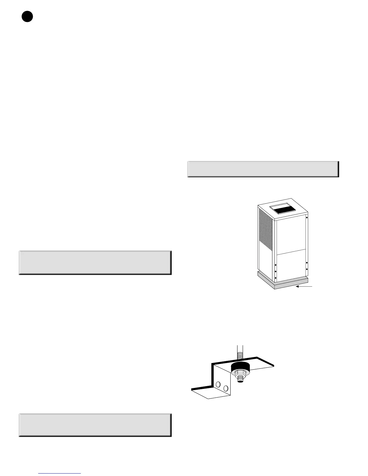
MOUNTING VERTICAL UNITS:
Vertical units up to
five tons are available
in left, right, front, or
rear air return
configurations.
Vertical units should
be mounted level on
a vibration absorbing
pad slightly larger
than the base to
minimize vibration
transmission to the
building structure. It
is not necessary to
anchor the unit to the
floor. (See Figure #1).
Vertical units larger than five tons should be vibration
isolated according to the design engineers specifications.
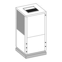
MOUNTING HORIZONTAL UNITS:
While horizontal units may be installed on any level
surface strong enough
to hold their weight,
they are typically
suspended above a
ceiling by threaded
rods. The rods are
usually attached to
the unit corners by
hanger bracket kits
(P/N 930-004, 006).
(See Figure #2). The
rods must be
securely anchored to the ceiling. Refer to the hanging
bracket assembly and installation instructions for details.
Models GO 042 and up require six brackets (930-
006).(See unit horizontal detail drawing). Horizontal units
installed above the ceiling must conform to all local
codes. An auxiliary drain pan if required by code, should
be at least four inches larger than the bottom of the heat
2
GO SERIES
(Figure #2)
(Figure #1)
VIBRATION
PAD
FULL SIZE