Serious damage or erosion of the water to refrigerant
heat exchanger could occur.
Always check carefully for water leaks and repair
appropriately. Units are equipped with female pipe thread
fittings. Consult the specification sheets for sizes. Teflon
tape sealer should be used when connecting water piping
connections to the units to insure against leaks and
possible heat exchanger fouling. Do not overtighten the
connections. Flexible hoses should be used between the
unit and the rigid system to avoid possible vibration. Ball
valves should be installed in the supply and return lines
for unit isolation and unit water flow balancing.
ELECTRICAL:
(Refer to electrical component box layout, Figure #5)
Field wiring must comply with local and national electric
codes. Power to the unit must be within the operating
voltage range indicated on the unit nameplate. or on the
performance data sheet. On three phase units (single
steps units only) phases must be balanced within 2%.
CAUTION: Operation of unit on improper line voltage or
with excessive phase imbalance will be hazardous to the
unit, constitutes abuse and may void the warranty.
Properly sized fuses or HACR circuit breakers must be
installed for branch circuit protection. See unit nameplate
for maximum fuse or breaker size.
The unit is provided with a concentric knock-out in the
front left corner post for attaching common trade sizes of
conduit, route power supply wiring through this opening.
Always connect the ground lead to the grounding lug
provided in the control box and power leads to the power
supply terminal block as indicated on the wiring diagram
and Figure #5.
NOTE: Units supplied with internal electric heat require
two (2) separate power supplies: one for the unit
compressor and one for the electric heater elements,
blower motor and control circuit. Refer to the ELECTRIC
HEATER PACKAGE OPTION section and Figure #8 and
#9 for wiring instructions, minimum circuit ampacities and
maximum fuse/breaker sizing.
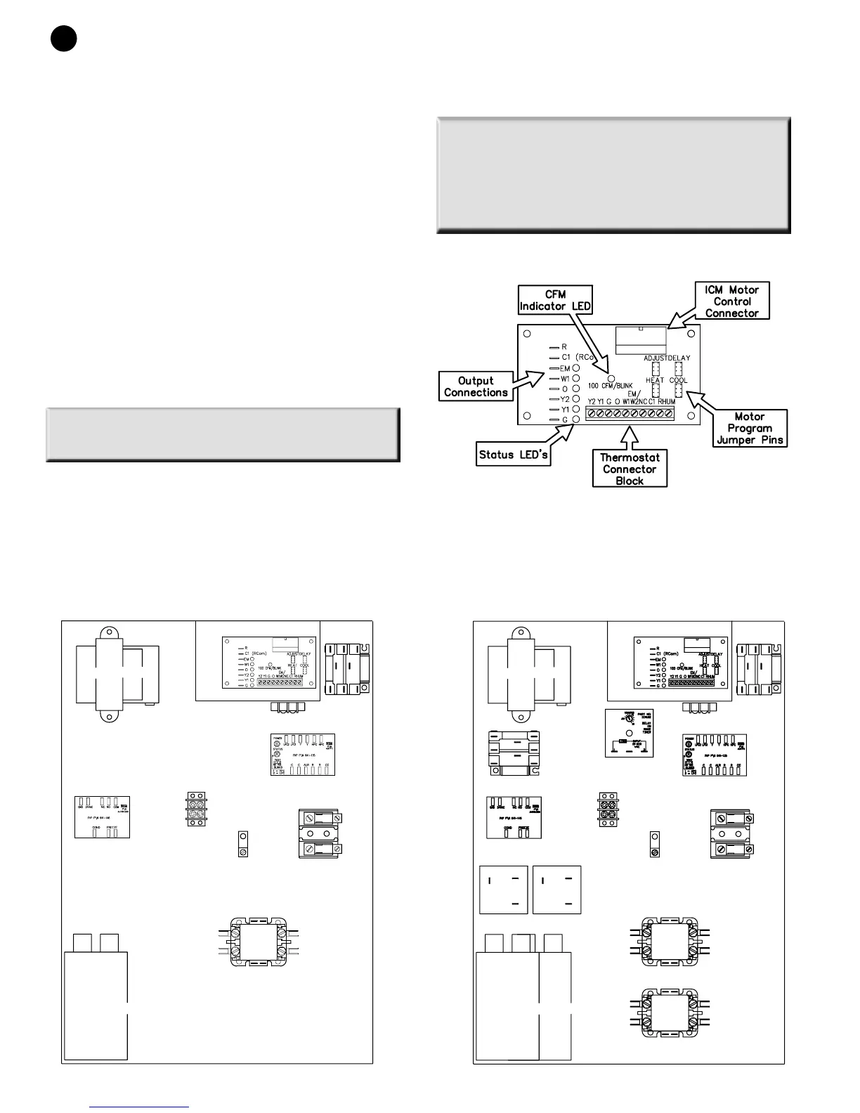
ICM INTERFACE BOARD:
THERMOSTAT CONNECTIONS:
Thermostat wiring is connected to the 10 pin screw type
terminal block on the lower center portion of the ICM
Interface Board. In addition to providing a connecting
4
GO SERIES
(Figure #6)
(Figure #5)
Electrical Box
Component
Layout