8
GO SERIES
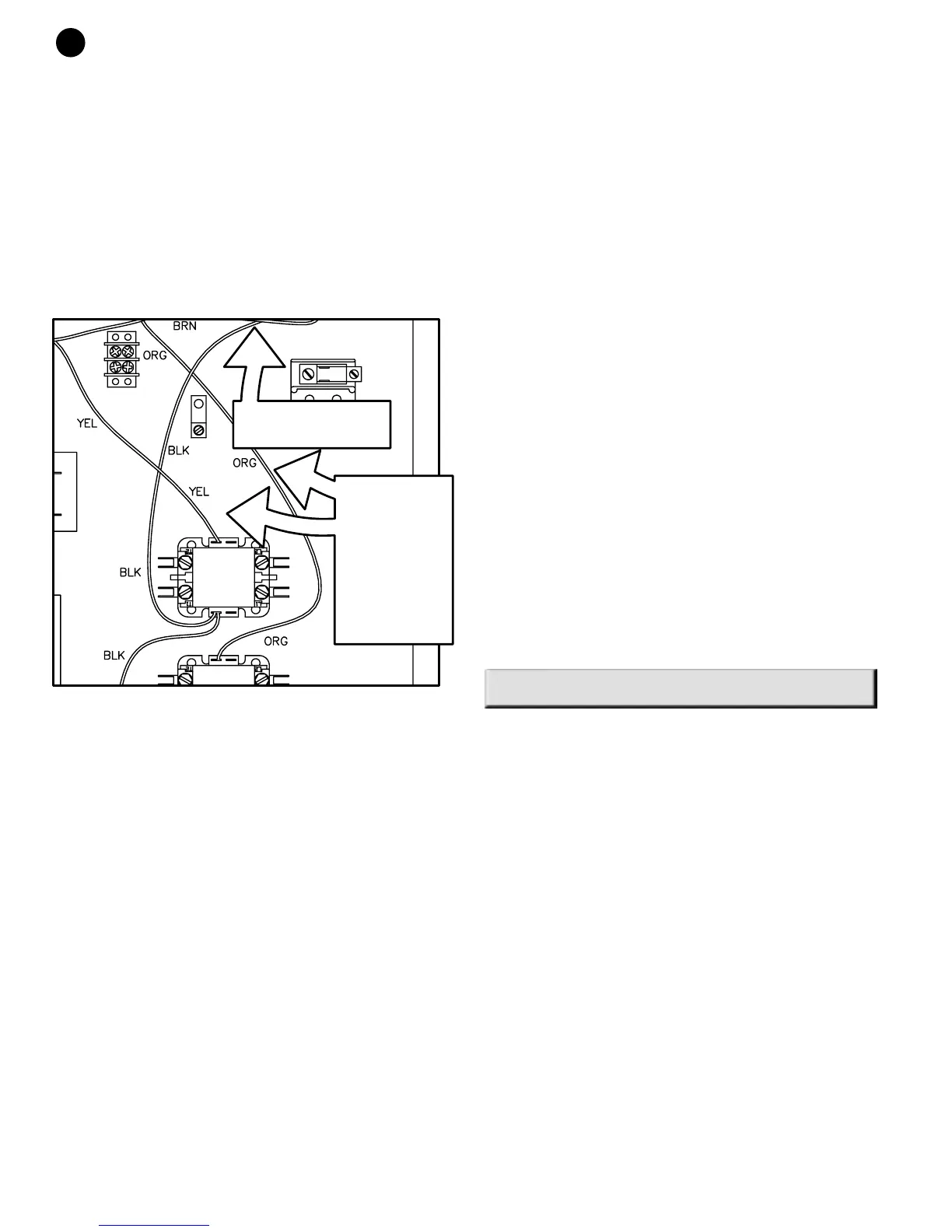
compressor contractor coil wires from CC1 to CC2 and
vice versa. Additionally the installer should set the time delay
relay to its minimum setting of 0.1 minutes to prevent
extended periods of the 40% compressor running alone with
full air flow. It is recommended that if the sequence of
operation is altered in this manner that the installer
replace the unit wiring diagram with the one shown in
Figure #18 to avoid confusion in the future.
The sequence of operation for this unit would basically be
the same as for a factory wired multi-step unit but with
the 60% compressor running in 1st stage and the 40%
compressor starting in 2nd followed immediately by the
60% compressor for full capacity.
WELL WATER SYSTEMS:
(Figure #11)
In well water applications water pressure must always be
maintained in the heat exchanger. This can be
accomplished with either control valve or a bladder type
expansion tank. When using a single water well to supply
both domestic water and the heat pump care must be
taken to insure that the well can provide sufficient flow for
both. In well water applications a slow closing solenoid
valve must be used to prevent water hammer.
Solenoid valves should be connected across Y1 and C1
on the interface board for multi-step units and Y2 and C1
for single step units. Make sure that the VA draw of the
valve does not exceed the contact rating of the
thermostat.
INSTALLATION OF PRESSURE
REGULATING VALVES:
Pressure regulating valves are used to increase or
decrease water flow through the heat pump in response
to refrigerant pressure. In some cases more water may
be required in heating than in cooling, or vice versa. With
the Geo-Miser heat pumps these valves are not required.
However, if installed, a pair of valves are required for
proper operation, one valve for cooling (direct acting) and
another valve for heating (indirect acting). A refrigerant
tap is provided in the refrigerant line located between the
reversing valve and the water-to-refrigerant heat
exchanger for proper monitoring of the refrigerant
pressures.
The discharge water from the heat pump is not
contaminated in any manner and can be disposed of in
various ways depending on local building codes (i.e.
discharge well, dry well, storm sewer, drain field, stream
or pond, etc.) Most local codes forbid the use of a
sanitary sewer for disposal. Consult your local building
and zoning department to insure compliance in your area.
COOLING TOWER/BOILER SYSTEMS:
(Figure #12)
The cooling tower and boiler water loop temperature is
usually maintained between 50˚ F to 100 ˚ F to assure
adequate cooling and heating performance.
In the cooling mode, heat is rejected from the FHP unit
into the water loop. A cooling tower provides evaporative
cooling to the loop water thus maintaining a constant
supply temperature to the unit. When utilizing open
cooling towers, chemical water treatment is mandatory to
ensure the water is free from corrosive elements. A
secondary heat exchanger (plate frame) between the unit
and the open cooling tower may also be used. It is
imperative that all air be eliminated from the closed loop
side of the heat exchanger to insure against fouling.
In the heating mode, heat is absorbed from the water
loop. A boiler can be utilized to maintain the loop at the
desired temperature.
CAUTION: Water piping exposed to extreme low
ambient temperatures is subject to freezing.
Consult the specification sheets for piping sizes. Teflon
tape sealer should be used when connecting to the unit
to insure against leaks and possible heat exchanger
fouling. Do not overtighten the connections. Flexible
hoses should be used between the unit and the rigid
system to avoid possible vibration. Ball valves should be
installed in the supply and return lines for unit isolation
and unit water flow balancing. Pressure/temperature
ports are recommended in both supply and return lines
for system flow balancing. Water flow can be accurately
set by measuring the water-to-refrigerant heat
exchangers water side pressure drop. See specification
sheets for water flow vs. pressure drop information.
Before final connection to the unit, the supply and return
hose kit must be connected together and the system
flushed to remove dirt, piping chips and other foreign
material. Failure to do so may cause poor unit
performance, heat exchanger damage and will void the
unit warranty.
EARTH COUPLED SYSTEMS:
(Figure #13)
Closed loop and pond applications require specialized
design knowledge.No attempt at these installations
should be made unless the dealer has received
specialized training. Utilizing FHP’s Ground Loop