pump. Plumbing connected to the heat pump must not
come in direct contact with joists, trusses, walls, etc..
Some applications require an attic floor installation of the
horizontal unit. In this case the unit should be set in a full
size secondary drain pan on top of a vibration absorbing
mesh. The secondary drain pan prevents possible
condensate overflow or water leakage damage to the
ceiling. The secondary drain pan is usually placed on a
plywood base isolated from the ceiling joists by additional
layers of vibration absorbing mesh. In both cases, a 3/4"
drain connected to this secondary pan should be run to
an eave at a location that will be noticeable. If the unit is
located in a crawl space, the bottom of the unit must be
at least 4" above grade to prevent flooding of the
electrical parts due to heavy rains.
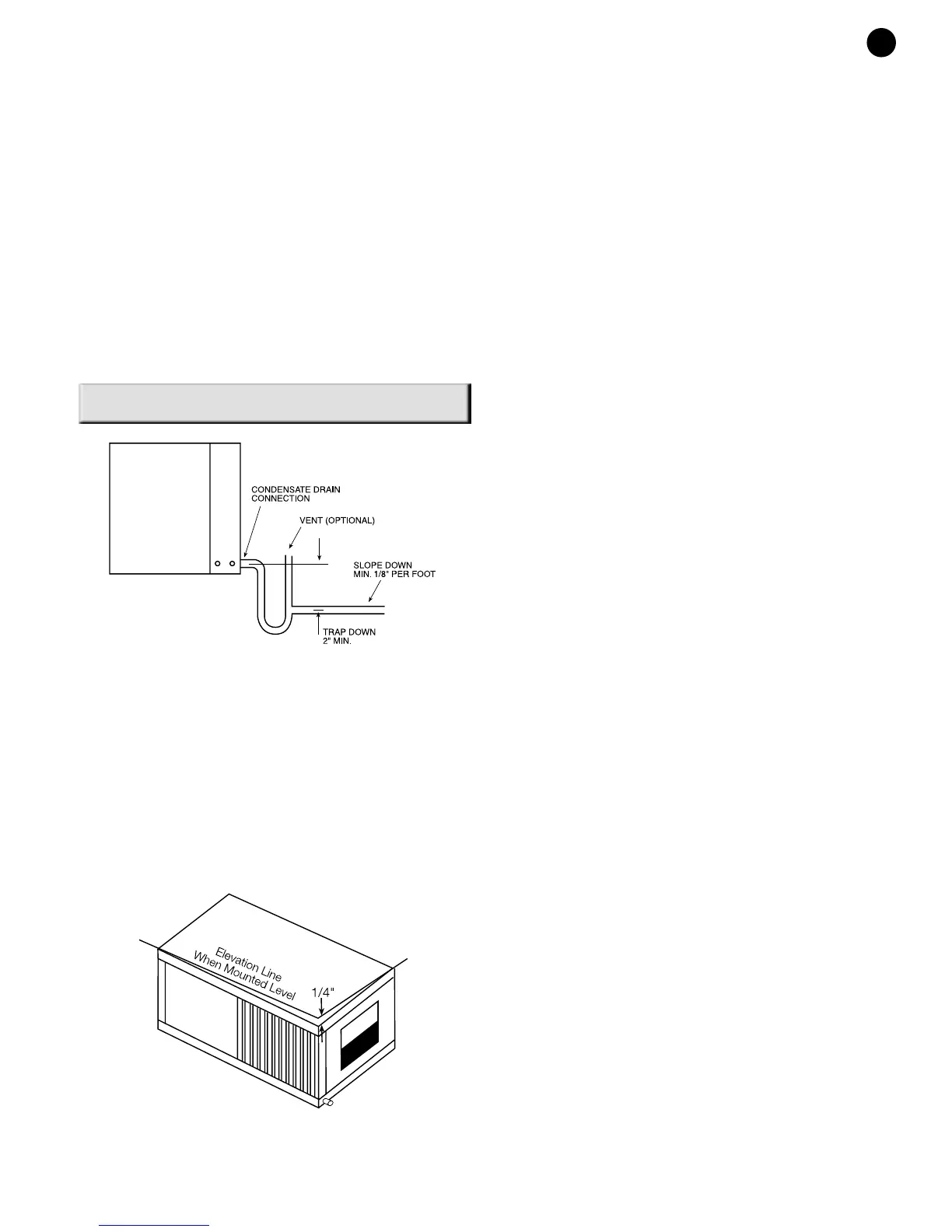
CONDENSATE DRAIN:
NOTE: If equipped with float style condensate overflow
switch, final adjustment must be made in the field.
All GO Units are equipped with a condensate overflow
sensor/switch. A drain line must be connected to the
heat pump and pitched away from the unit a minimum of
1/8" per foot to allow the condensate to flow away from
the unit.
This connection must be in conformance with local
plumbing codes. A trap must be installed in the
condensate line to insure free condensate flow. (Heat
Pumps are not internally trapped). A vertical air vent is
sometimes required to avoid air pockets. (See Figure #3).
The length of the trap depends on the amount of positive
or negative pressure on the drain pan. A second trap
must not be included.
The horizontal unit should be pitched approximately 1/4"
towards the drain in both directions, to facilitate
condensate removal. (See Figure #4)
DUCT SYSTEM:
A supply air outlet collar and return air duct flange are
provided on all units to facilitate duct connections. Refer
to the FHP individual data specification sheet for physical
dimensions of the collar and flange.
A flexible connector is recommended for supply and
return air duct connections on metal duct systems. All
metal ducting should be insulated with a minimum of one
inch duct insulation to avoid heat loss or gain and prevent
condensate forming during the cooling operation.
Application of the unit to uninsulated duct work is not
recommended as the unit’s performance will be adversely
affected. Do not connect discharge ducts directly to the
blower outlet. The factory provided air filter must be
removed when using a filter back return air grill.The
factory filter should be left in place on a free return
system.
If the unit will be installed in a new installation which
includes new duct work, the installation should be
designed using current ASHRAE procedures for duct
sizing. If the unit is to be connected to existing ductwork,
a check should be made to assure that the duct system
has the capacity to handle the air required for the unit
application. If the duct system is too small, larger
ductwork should be installed. Check for existing leaks
and repair.
The duct system and all diffusers should be sized to
handle the designed air flow quietly. To maximize sound
attenuation of the unit blower, the supply and return air
plenums should be insulated. There should be no direct
straight air path thru the return air grille into the heat
pump. The return air inlet to the heat pump must have at
least one 90 degree turn away from the space return air
grille. If air noise or excessive air flow are a problem, the
blower speed can be changed to a lower speed to
reduce air flow. (Refer to ICM motor interface board
section in this manual and Figure #7)
PIPING:
Supply and return piping must be as large as the unit
connections on the heat pump (larger on long runs).
Never use flexible hoses of a smaller inside diameter than
that of the fluid connections on the unit. GT Units are
supplied with either a copper or optional cupro-nickel
condenser. Copper is adequate for ground water that is
not high in mineral content. Should your well driller
express concern regarding the quality of the well water
available or should any known hazards exist in your area,
we recommend proper testing to assure the well water
quality is suitable for use with water source equipment. In
conditions anticipating moderate scale formation or in
brackish water a cupro-nickel heat exchanger is
recommended.
Both the supply and discharge water lines will sweat if
subjects to low water temperature. These lines should be
insulated to prevent damage from condensation.
All manual flow valves used in the system must be ball
valves. Globe and gate valves must not be used due to
high pressure drop and poor throttling characteristics.
Never exceed the recommended water flow rates.
3
GO SERIES
(Figure #3)
(Figure #4)