AN5116-06B/AN5516-06/AN5516-04 Optical Line Terminal Equipment Hardware Description
Working Principle
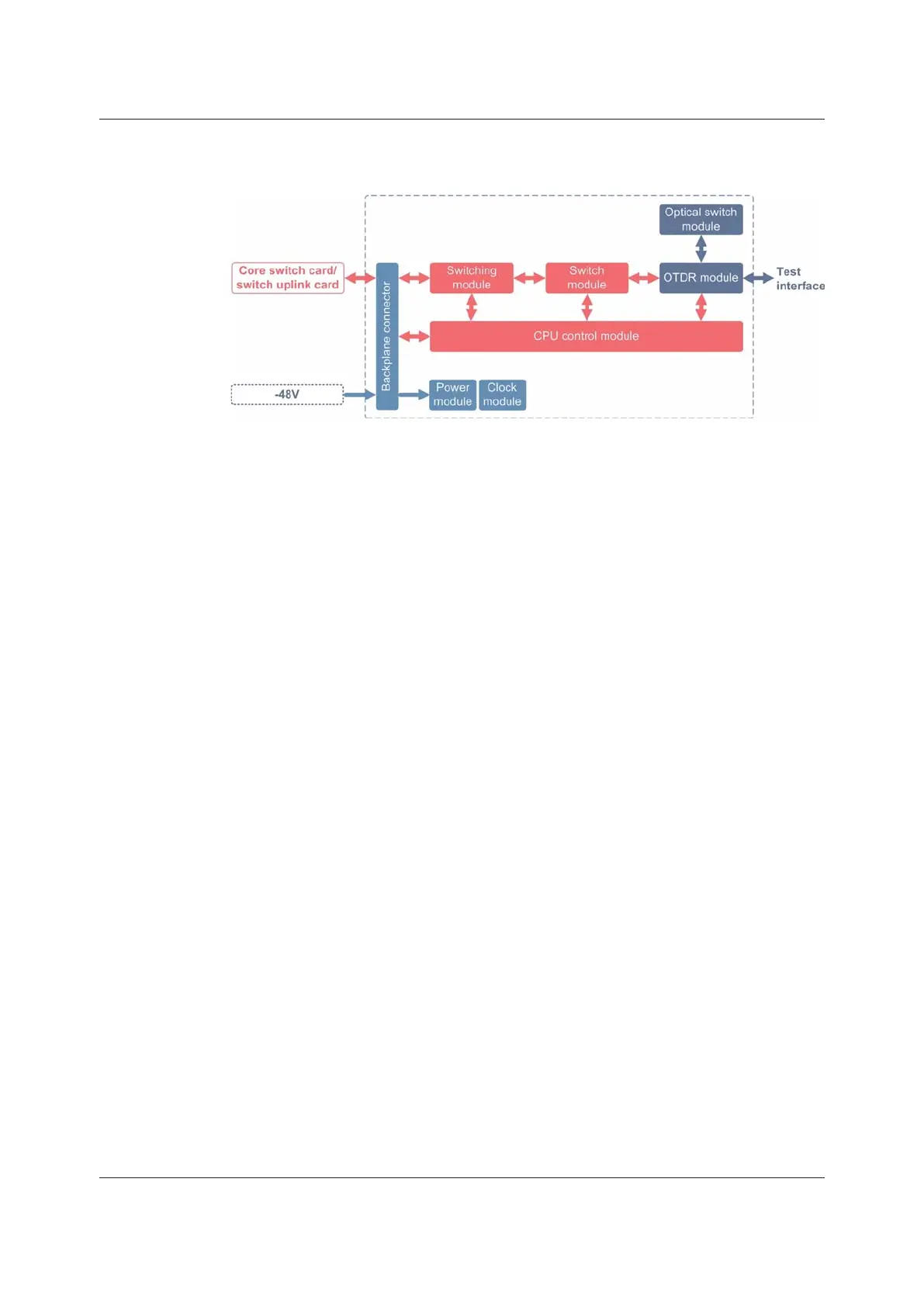
Figure 3-45 Working Principle of the ODMC Card
u The optical switch module is used to extend the test ports.
u The OTDR module transmits the test optical signals and analyzes the reflected
signals to ascertain the fault conditions of the optical fiber link.
u The switch module aggregates the signals from the ports.
u The switching module performs the active-standby switching of the 10G signals
and the 100 M out-of-band management ports on the backplane.
u The CPU control module loads the card software, controls the card operation,
and manages the card.
u The power module supplies power to each functional module of the card.
u The clock module provides clock signals for each functional module of the card.
3.14 Other Cards
This section introduces the basic information, panels, technical parameters,
interface specifications, functions and working principles of the clock card and the
common interface card.
3.14.1 TIMA
Basic Information
Overview of Cards shows the number, matching subracks and power consumption
of the card.
136 Version: C
 Loading...