3 Card
u The switch module aggregates signals on16 lines from the ports.
u The control module loads the card software, controls the card operation, and
manages the card.
u The power module supplies power to each functional module of the card.
u The clock module provides clock signals for each functional module of the card.
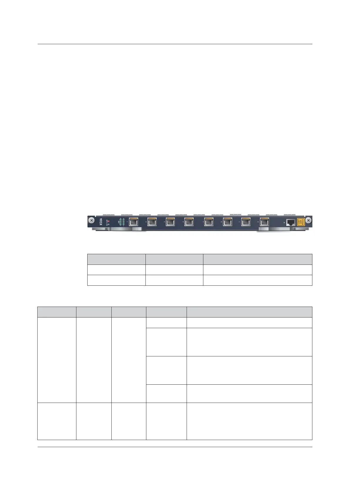
3.7.5 XG8A
Basic Information
Overview of Cards shows the number, matching subracks and power consumption
of the card.
Panel Description
Table 3-37 Interfaces
Identifier Meaning Description
1 to 8 10G EPON interface Connected to a remote ONU via an ODN.
D
Debugging interface RJ-45 debugging serial port
Table 3-38 Indicator LEDs
Identifier
Meaning
Color Status
Description
ACT
Working
indicator
LED
Green
ON
The card is working normally.
Blinking slowly
The card is being initialized or the software is being
started. The communication link between the active
and standby cards is not set up.
Blinking
quickly
The card is receiving a configuration command or
the communication link between the active and
standby cards is being set up.
OFF
The card is not powered on or the software is not
started.
ALM
Alarm
indicator
LED
Red ON
The card has alarms for fiber disconnection, light
leakage, and absence of optical module at the PON
port, or the communication between the active and
standby cards is interrupted.
Version: C 73
 Loading...