Doc. P/N 8.8517.00.6
Rev. December, 2019
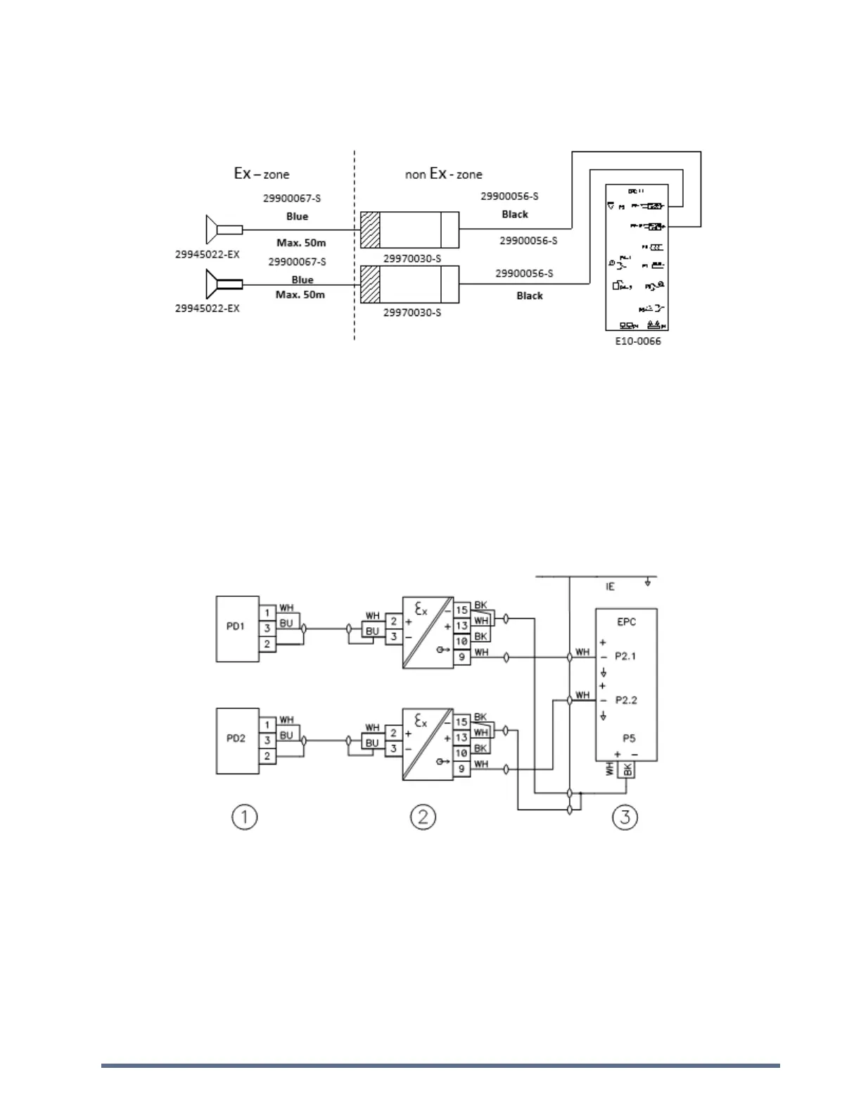
2.2. Intrinsically Safe Connection to EPC
2.2.1. Single Wire Diagram (Schematic)
Notes:
To ensure a solid functionality the cable length between detector and barrier may not exceed 50m.
Intrinsic safe transducer barrier + black cable + EPC placed outside Ex-zone.
Switch off EPC before connecting barrier and/or detector.
Intrinsic safe transducer barrier may only be placed outside Ex-zone, as close as possible to the EPC
controller.
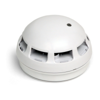
2.2.2. Wiring Diagram
1) Intrinsic safe transducer barrier PN: 29970030-S: one barrier for each detector.
2) EPC controller PN: E10-0066. Use RE2Y(ST)Y (black 1x2x0.75mm²) cable for connection to Intrinsic safe transducer
barrier.
2.2.3. Intrinsic Safety Calculation
The worked out example below, for 50 m blue cable, shows the calculation method to verify compliance to intrinsic
safety requirements in accordance to EN50 020 and EN50 039.