Doc. P/N 8.8517.00.6
Rev. December, 2019
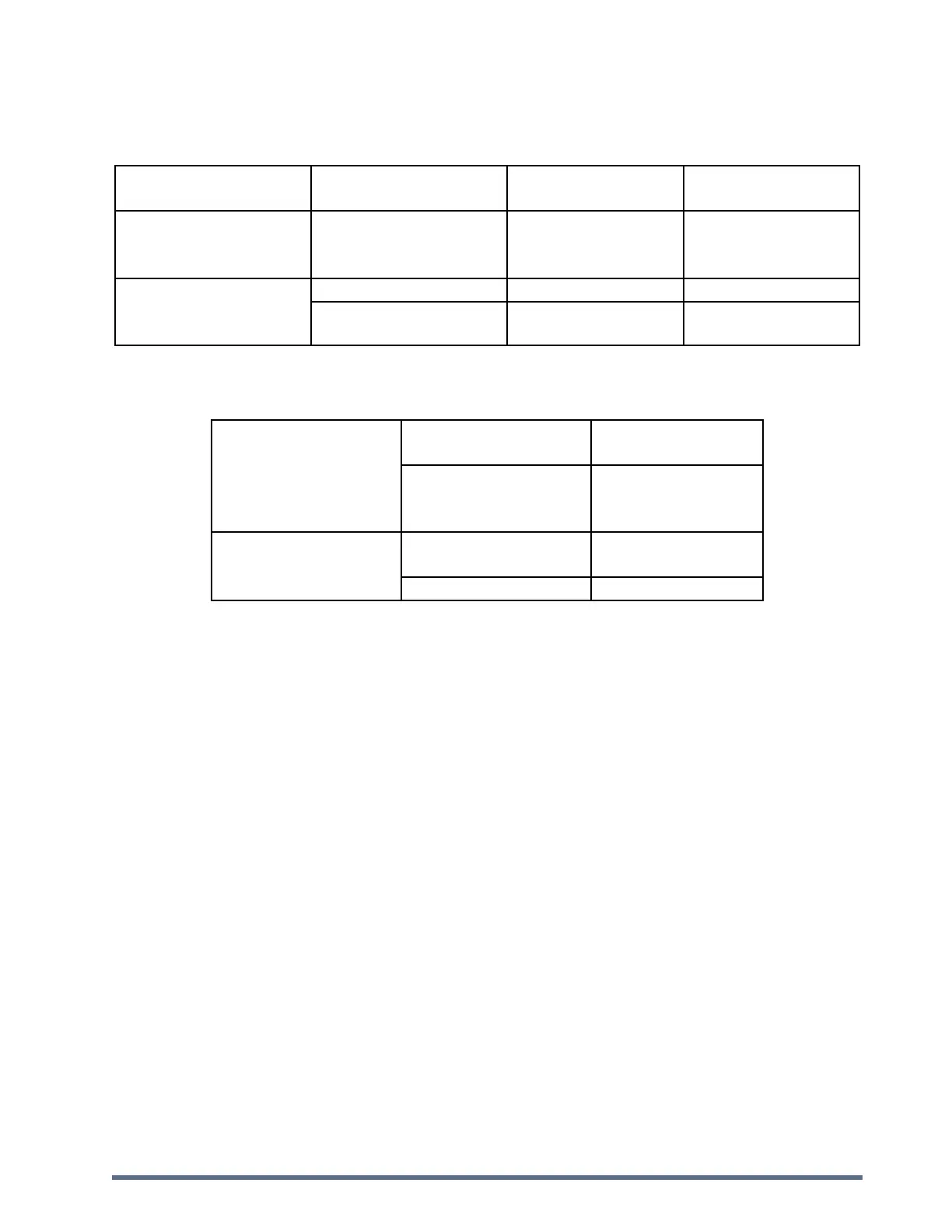
1.3. Clarification of the Temperature Classes
1.3.1. ATEX
Maximum process
temperature
Part of the equipment
situated in Category 1
(zone 0/20)
T 85 °C
T 100 °C
T 130 °C
Part of the equipment
situated in Category 2
(zone 1/21)
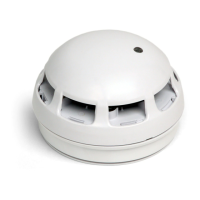
1.3.2. IECEx
Part of the equipment
situated in zone 20
Maximum process
temperature
T 85 °C
T 100 °C
T 135 °C
Part of the equipment
situated in zone 21
Maximum ambient
temperature
1.4. Hazardous Area Information
1.4.1. Cerex (D) – Explosion Protection Ceramic Pressure Detector ‘Dust’
This detector is suitable for installation in:
Dust Ex areas: installation into zone 21 (and 22) and wetted parts in contact with zone 20.
1.4.2. Cerex (G/D) – Explosion Protection Ceramic Pressure Detector ‘Gas’
This detector is suitable for installation in:
Dust Ex areas: installation into zone 21 (and 22) and wetted parts in contact with zone 20
Gas Ex areas: installation into zone 1 (and 2) and wetted parts in contact with zone 0.
When installed in Gas Ex zones, an Eex(i) intrinsic safe separation barrier shall be used (installed in an non-
hazardous area, typically in Fike EPACO enclosures).
1.4.3. Conditions for Special Use
For the equipment with a permanently connected cable, the user will have to connect the free extremity of cable
either in a non-explosive atmosphere, or in an enclosure protected by a recognized protection mode adapted to the
area.