Doc. P/N 8.8517.00.6
Rev. December, 2019
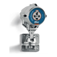
EEx ia detector (P/N 2994502201-C-S (FDA approved) and 29945022-C-S (not FDA approved)) placed inside Ex zone
Cable Belden 9463NH (blue 0.75mm²) PN 29900044 used to route detector into non-Ex zone
km (used as default 50 m)
Associated apparatus: Intrinsic safety Barrier PN 29970041-S placed outside Ex zone
EEx ia II C
TUV 00 ATEX 1522
Comparison for intrinsic safety compliance:
3. OPERATION
Fike’s EPC and EPACO components offers extensive display and/or evaluation possibilities for verifying the ceramic
detector correct functioning.
For more information, please contact your nearest Fike representative and/or EPC Manual E06-051-x.
4. MAINTENANCE
Caution: If assistance is needed, contact Fike for instructions, before performing any maintenance or service work on
the Fike Explosion Protection Equipment and/or System.