Doc. P/N 8.8517.00.6
Rev. December, 2019
2. WIRING INSTRUCTIONS
The Ceramic Pressure Detector shall only be connected to the Fike EPC (Explosion Protection Controller) in accordance
with following instructions. When connecting devices with explosion protection certificates, please comply with
national standards, warnings and wiring diagrams listed in the additional explosion protection documentation
accompanying these Operating Instructions.
2.1. Connecting 4-20 mA Output to EPC (P2-1 or P2-2)
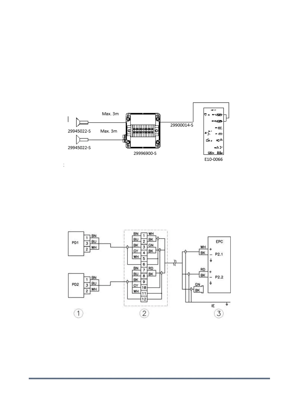
2.1.1. Single Wire Diagram (Schematic)
Notes:
Use Belden 9873 cable between EPC and Junction Box.
Do not connect to other terminals besides the terminals P2-1 and P2-2 of the EPC Fike Controller.
Switch off EPC before connecting to the junction box.
Maximum cable loop resistance from detector to EPC is 30 Ω.
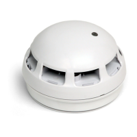
2.1.2. Wiring Diagram
1) Pressure Detector PN: 29945022-S to be wired using Belden 9873 (gray 3x2x0.5mm²) cable PN 29900014-S (roll of
50m).
2) Junction Box PN: 29996900-S, includes terminals for connecting up to 2 detectors.
3) EPC controller PN: E10-0066.