EXPLOSION ISOLATION VALVE
INSTALLATION & OPERATION MANUAL
January, 2015 Document P/N: E06-017-1 (Rev 2) Page: 9
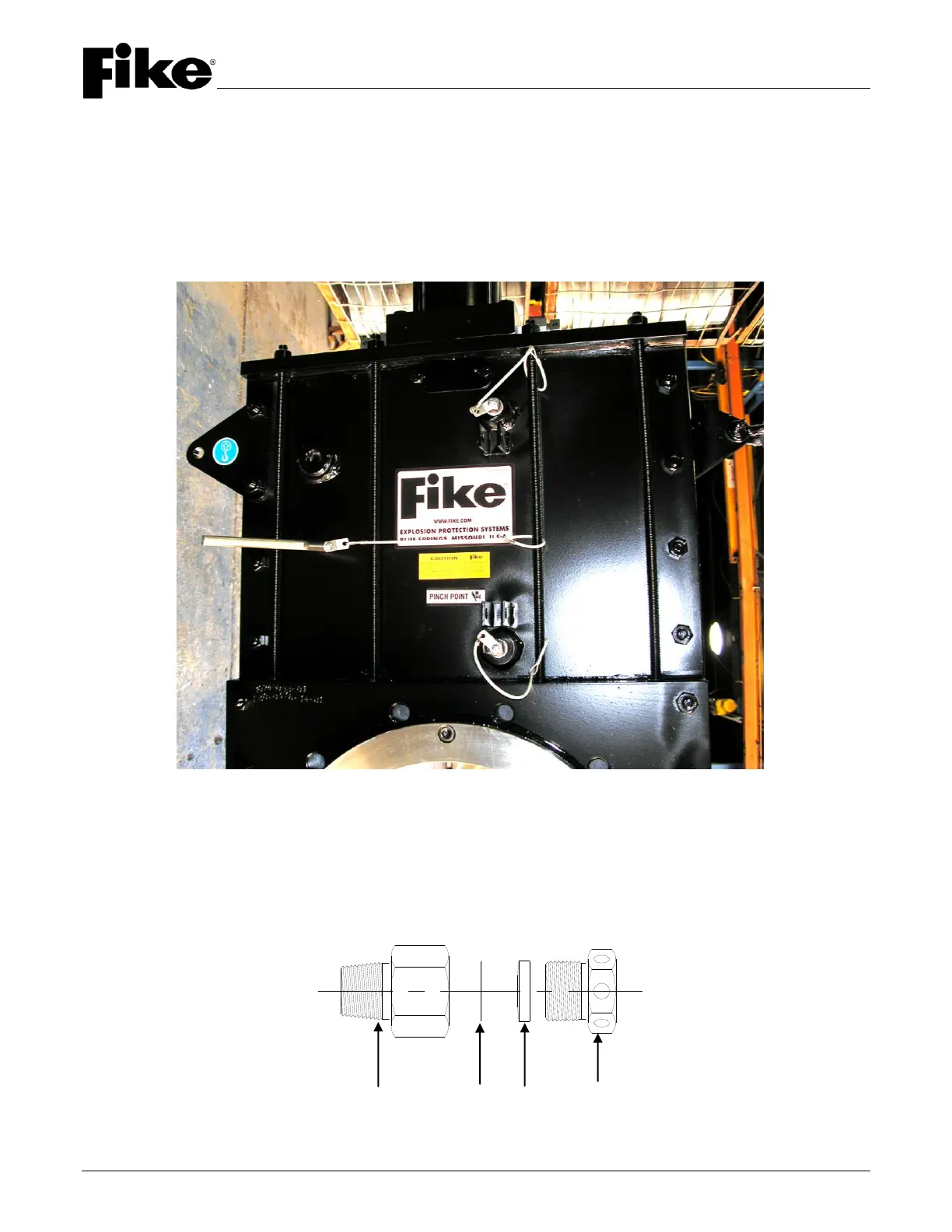
2.5 LOCKOUT PIN
The valves have been designed with lockout pins to enable the EIV to be locked in either the open or closed
position.
WARNING: The lockout pin is not intended to prevent the EIV from being closed by the GCA. The lockout pin
will only prevent the EIV gate from moving during maintenance.
When the lockout pins are not being used, the plugs (with thread tape) must be installed in the threaded holes to
prevent moisture and debris from entering the valve body (Refer to Figure 6).
FIGURE 6 – LOCKOUT PIN
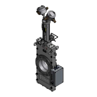
2.6 MUFFLER
The muffler is a device that allows for the exhaust of the air below the piston when the valve closes as a result of
an activation. It contains a clear Teflon seal that prevents the entrance of moisture and other contaminants into
the actuating cylinder. Upon valve activation, the seal is punctured by the rapidly escaping gases. The seal in
each muffler is replaced during valve refurbish procedures (Refer to Figure 7).
FIGURE 7 – MUFFLER
Muffler Base Seal Retainer Outlet