EXPLOSION ISOLATION VALVE
INSTALLATION & OPERATION MANUAL
January, 2015 Document P/N: E06-017-1 (Rev 2) Page: 3
2.1.2 VALVE LOCATION
The Fike EIV must be installed at the specific location as detailed on the system design drawing. Failure to locate
the EIV as detailed on the system drawing could result in the protection system being unable to stop the flame
front, potentially causing catastrophic failure and injury to plant personnel. Careful consideration should be taken
when mounting and supporting the EIV.
2.1.3 SUPPORT CONSIDERATIONS
Valves shall be supported to prevent damage to the valve, process line and the process facility during activation.
Refer to Table 4 and Figures 9 and 10 for EIV physical specifications. Mounting may be accomplished by
attaching to the support points on the valve body. The EIV shall not be used to support the piping. The valve
must be supported independently from the process piping by directly supporting with structures connected to the
valve, and additional structures connected to the process piping within 3 feet of each side of the valve.
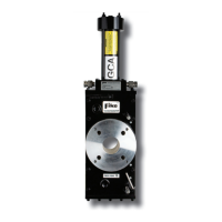
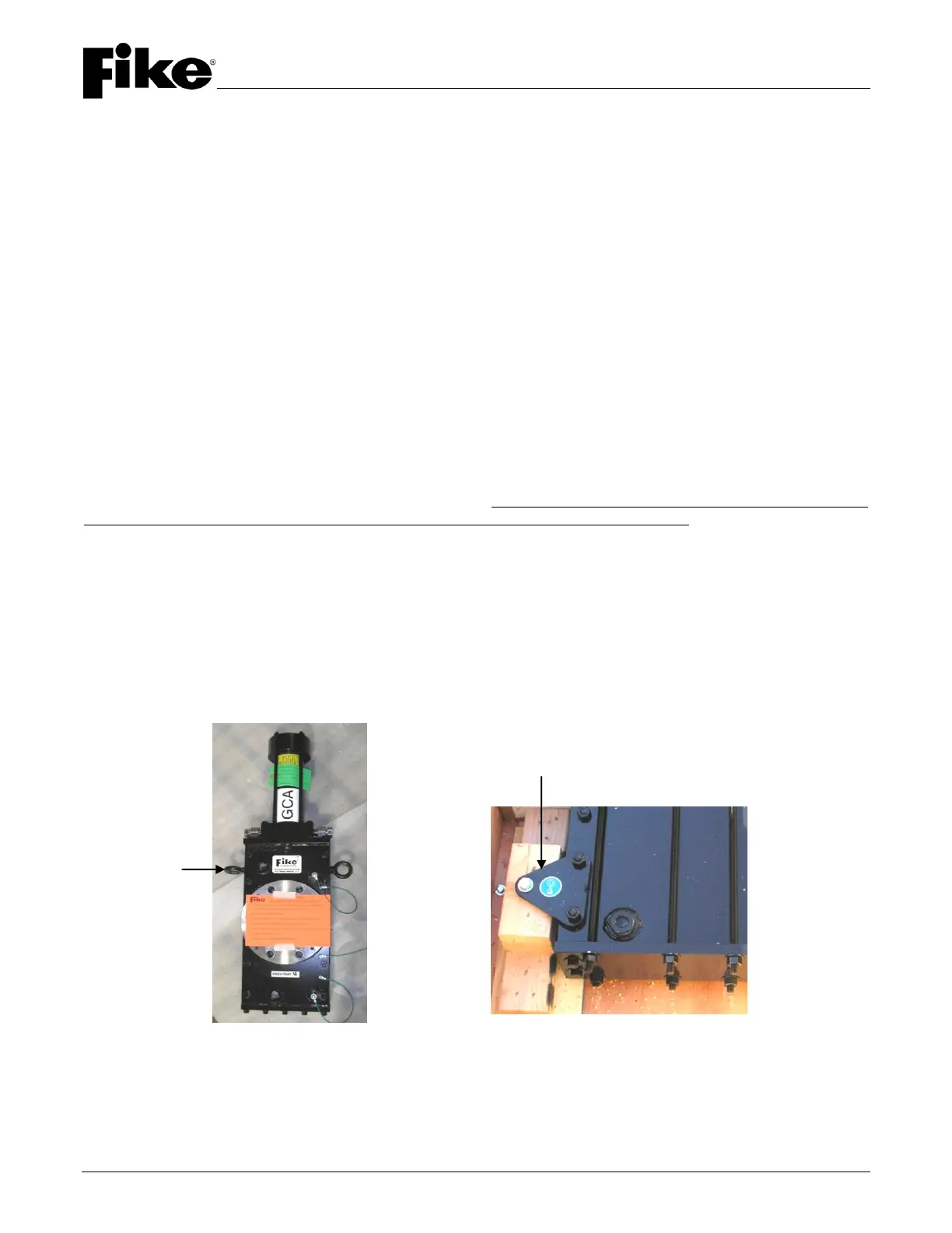
Valve sizes 2", 3" and 4" have two (2) lift eye-bolts attached to the valve body, one on each edge. Valve sizes 6",
8" and 10" have four (4) lift eye-bolts, two on each edge. These lifting eyes may be removed to utilize the ½"-13
threaded holes for support attachments. Valve sizes 12" through 24" have four (4) lift/support gussets at the top
and bottom of the valve body. These are provided as a convenient lifting point as well as for permanent support
attachment (refer to Figure 2).
The EIV shall be attached to the process line flanges using studs and nuts rather than bolts. The use of bolts
may cause deformation of internal components of the EIV and prevent proper operation. The EIV shall not be
used to pull or align the piping when installing the system. Flange studs shall be installed at a maximum torque of
10 ft-lb. Additional torque will damage internal valve components and prevent operation. Studs must be threaded
into the valve body to 1.5 times the stud diameter.
The thrust forces generated when the valve activates must be considered when fabricating support for the valve.
The gate damper in the bottom of the valve body absorbs most of this force. In addition, there is a counter-
reacting force in the opposite direction of the gate travel. This is caused by the pressure in the actuating cylinder
exerting a force on the upper end cap of the cylinder.
It is suggested to incorporate adjustment devices such as turnbuckles or jack screws when attaching to the valve
to facilitate balancing between the valve and the piping to prevent binding that would restrict gate movement.
Refer to Table 1 for valve weights and dynamic loads.
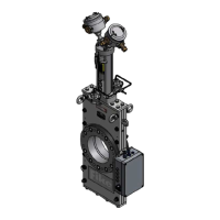
2" – 10" Valves 12" – 24" Valves
FIGURE 2 – VALVE LIFTING POINTS