EXPLOSION ISOLATION VALVE
INSTALLATION & OPERATION MANUAL
January, 2015 Document P/N: E06-017-1 (Rev 2) Page: 2
2.0 GCA ACTUATED ISOLATION VALVE – E30-016-XX-YY
2.1 INSTALLATION
2.1.1 MOUNTING ORIENTATION
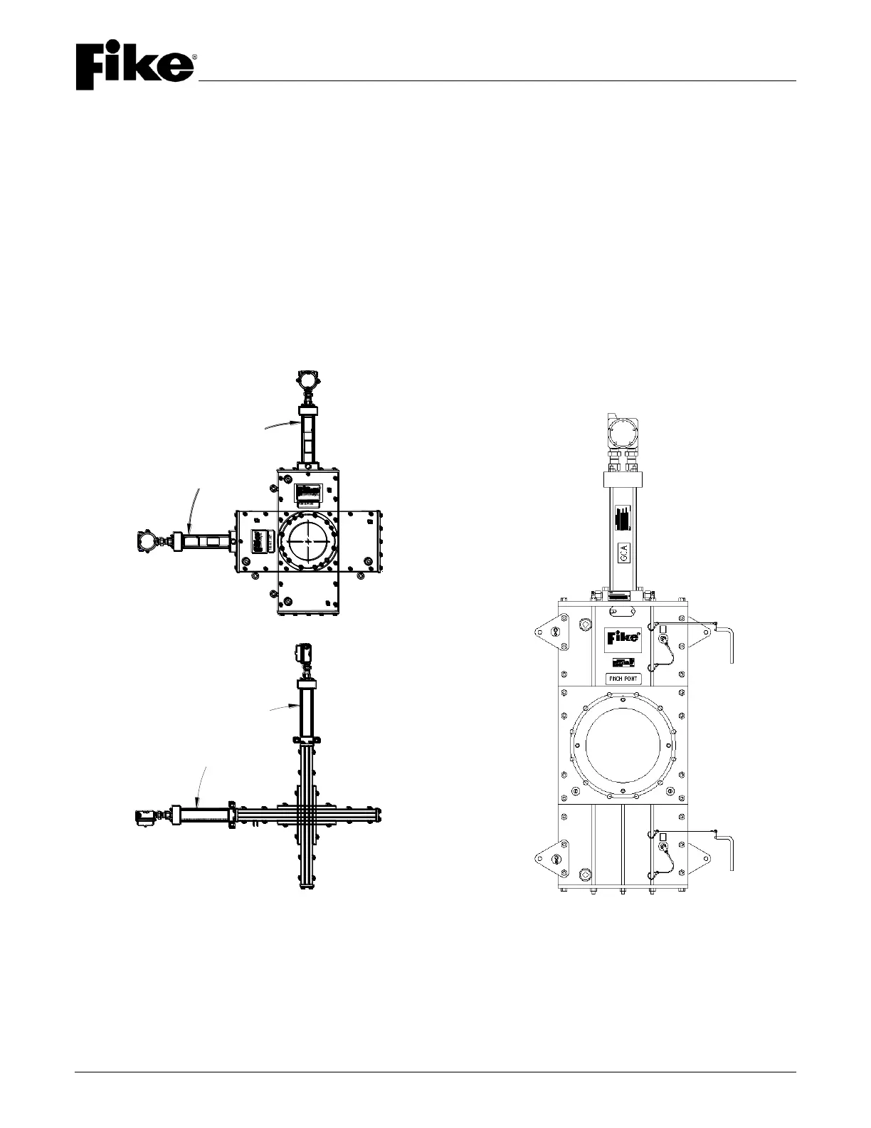
The valve must be oriented so that the gate is not moving upwards while closing. Valve sizes up through 18"
shall be positioned within the limits shown below, and valve sizes 20" and 24" shall only be mounted in an upright
position so that the gate travels downward during closure (refer to Figure 1).
For ease of maintenance a two foot removable process line section may optionally be installed on either side of
the valve. Additionally, an area of approximately two feet around the EIV should be left clear to allow access to
EIV components for maintenance and rebuild procedures.
Installing a weather cover is strongly suggested for an outdoor installation of an EIV. This will help shield against
rain and precipitation.
2" – 18" Mounting Orientation 20" and 24" Mounting Orientation
FIGURE 1 – MOUNTING ORIENTATION
GCA
All maintenance shall be performed by
FIKE certified technicians only. The
GCA leads shall be electrically
disconnected and shunted and the GCA
removed from the valve before
performing any maintenance. Reference
the Fike I&O Manual, E06-018.
All maintenance shall be performed by
FIKE certified technicians only. The
GCA leads shall be electrically
disconnected and shunted and the GCA
removed from the valve before
performing any maintenance. Reference
the Fike I&O Manual, E06-018.
GCA
Valve shall be
mounted within
90° of vertical
(Side to Side)
Valve shall be
mounted within
90° of vertical
(Front to Rear)