FIK-IR3-HD User Manual Doc. No. 06-932.02
For more information & Technical support: (800)-979-FIKE (3453) 13
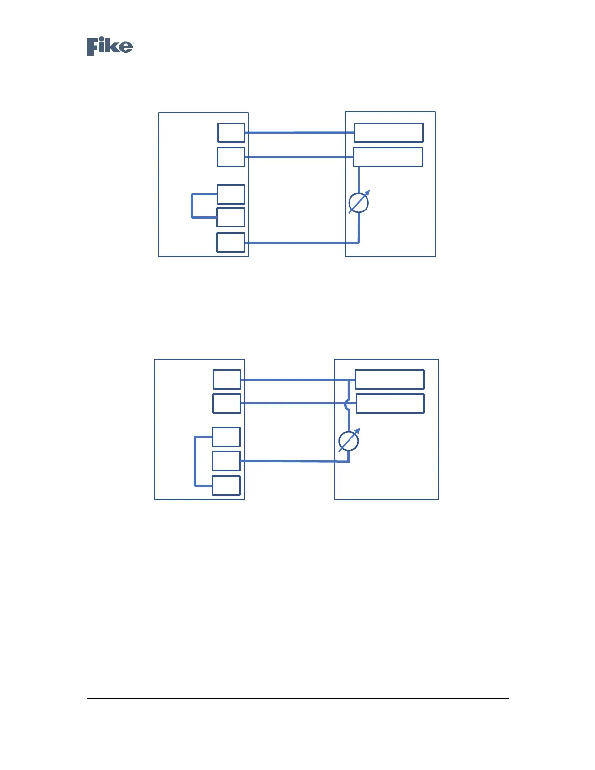
The following drawing shows how to wire the detector to act as a current source non-isolated transmitter (3-
wire connection):
Figure 6 - Source 3 - Wire Scheme
The following drawing shows how to wire the detector to act as a current sink non-isolated
transmitter (3-wire connection):
Figure 7 - Sink 3 - Wire Scheme
4.3 RS-485 Communication Network
Using the RS-485 network capability of the detector and communicator software, it is possible to
connect up to 32 detectors in an addressable system with 4 wires only (2 for power and 2 for
communication). Using repeaters, the number of detectors can be much larger (32 detectors for each
repeater) up to 247 on the same 4 wires. Using the RS-485 network, it is possible to read each
detector’s status (fault, alarm) and to initiate a BIT to each detector individually.
The detector communicates via RS-485 with a Modbus RTU compatible protocol. For more details on
the communication protocol, please consult with FIKE.

 Loading...