7
INSTALLATION INSTRUCTIONS
! Important Note: The Calibration system will take all the bends and restriction
of the flex hose into account and provide optimal performance.
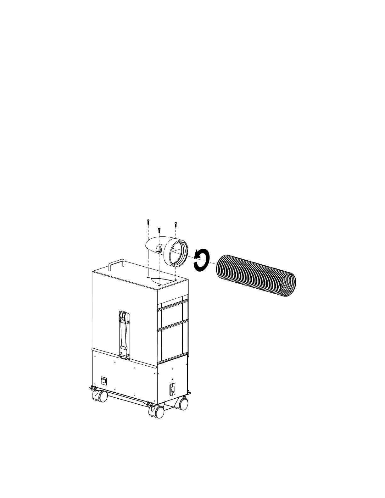
1. Install the Threaded Inlet onto the Lid Module using the three screws and the tool provided
with the user manual. See figure below.
2. Screw the supplied 4” Flex Hose onto the inlet of the machine. Insert the hose into the threads
and turning anti-clockwise until it can longer turn. See figure below.
3. Secure the other end of the supplied 4” Flex Hose to your laser with the supplied Hose Clamp.
4. Place the Filtrabox Micro in the final position that it will be regularly used. This is important for
Calibration as the system will take all the bends and flow restrictions of the flex hose into
account and provide optimal performance.
5. Install the supplied power cord onto the back of the Filtrabox Micro and turn it on with the Main
Power Switch located to the right of the User Interface.