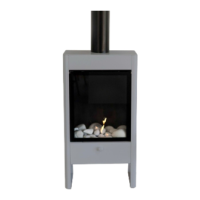
Front Cover Removal Process
• Carefully fully open and then remove the door panel, which is
held in place by 1 x 5mm cap screw in each lower corner and
held shut at the top with a magnet.
• Remove the front cover, which is held in place by 9 x 5mm cap screws,
3 at each side and 3 underneath. Due to the wiring connecting the
switch (on the cover panel) to the controller, the cover panel will need to
be lowered carefully and remain close to its original position.
…………………..
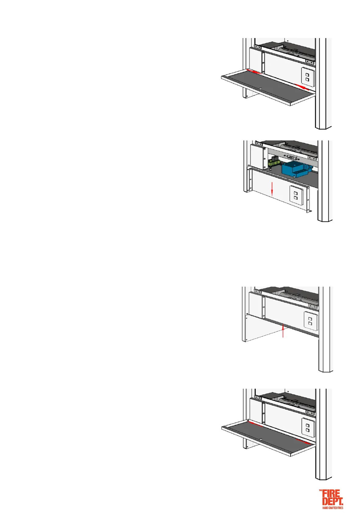
Front Cover Installation Process
• Fit the front cover, which is held in place by 9 x 5mm cap screw, 3 at
each side and 3 underneath. Note: There is wiring connecting the
switch (on the cover panel) to the controller. The cover panel will need
to be lifted carefully back into position.
• Fit the door panel, which is held in place by 1 x 5mm cap screw
in each lower corner and held shut at the top with a magnet.
Note: Do not over tighten the cap screws as they serve as the
hinge.