Installation of Optional Modules Installation
MS-2/MS-4 PN 51512:D 10/18/04 25
2.6 Installation of Optional Modules
CAUTION: Remove all power (AC and DC) before installing or removing modules or
wiring.
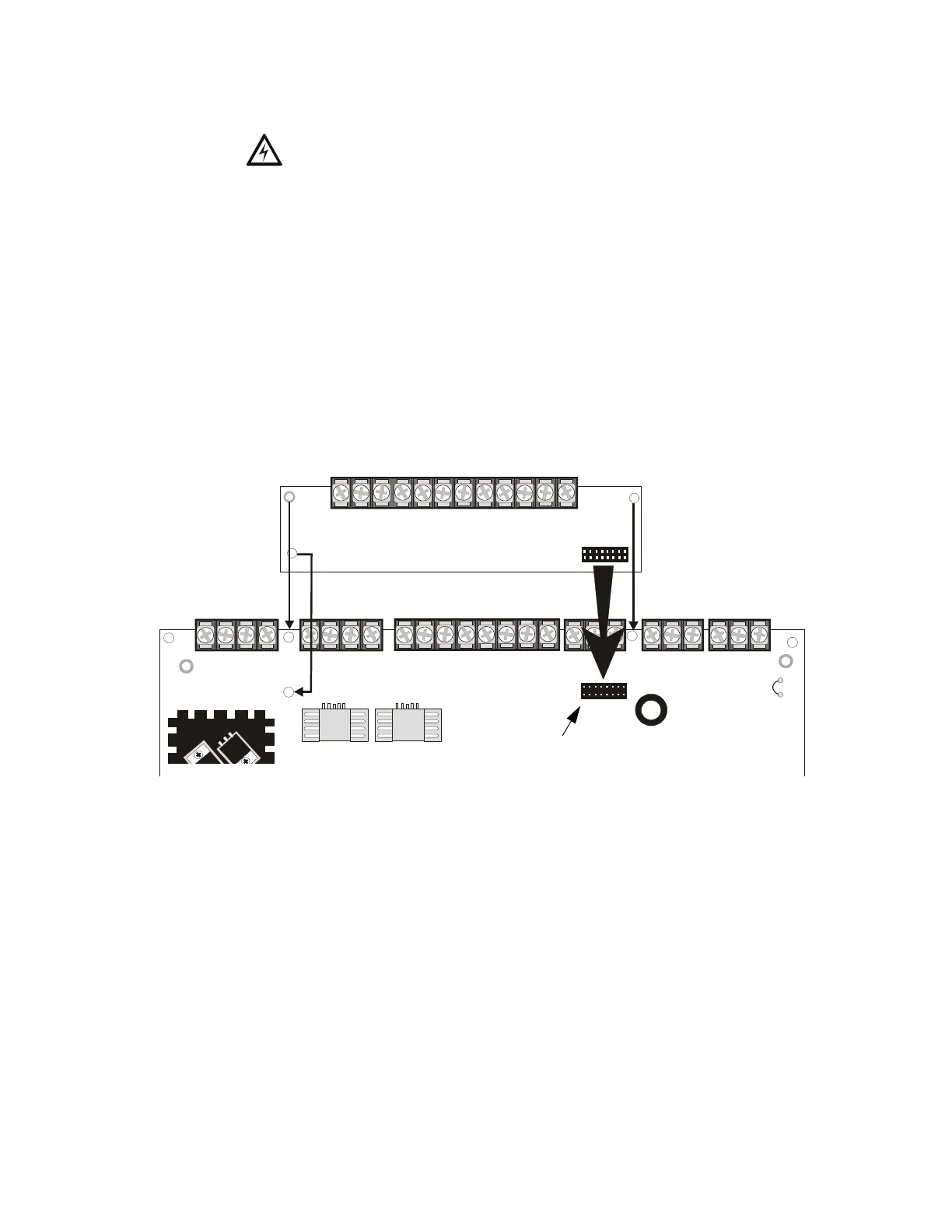
2.6.1 CAC-4 Class A Converter Module (MS-4 only)
2.6.1.1 Installation
The CAC-4 Module can be used to convert the four Style B (Class B) Initiating
Device Circuits to Style D (Class A) and the two Style Y (Class B) Notification
Appliance Circuits to Style Z (Class A). The module plugs into connector J1 which
is located at the top right of the MS-4 main circuit board.
Install the three supplied standoffs in the holes on the main circuit board as
indicated in the following figure. Carefully align the connector on the CAC-4 with
J1 on the FACP main circuit board and press the module securely into place. Make
certain the pins are properly aligned to prevent bending or breaking of any
connector pins.
TB1
TB2
TB3
TB5
TB6
TB7
J1
B+ B- B+ B-
NAC 1 NAC 2
+ - + -
Nonreset Reset
B+ B- B+ B-
ZONE 1 ZONE 2
B+ B- B+ B-
ZONE 3 ZONE 4
C TRBL NORM
TROUBLE
C NC NO
ALARM SUPV
C NC NO
CLASS A
CONVERTER
TB1
A+ A- A+ A-
NAC 1 NAC 2
CLASS A CLASS A
A+ A- A+ A-
ZONE 1 ZONE 2
CLASS A CLASS A
A+ A- A+ A-
ZONE 3 ZONE 4
CLASS A CLASS A
JP3
Figure 2.10 CAC-4 Module Installation
J1 Connector
MS-4 Main Circuit Board
Secure to Standoffs
Secure to Standoff
CAC-4 Module
ms4tocac.cdr