10 MS-9050UD Series PN 52413:D 12/15/08
FIRE ALARM
AC POWER
TROUBLE
1
4
7
*
2
3
1
5
6
89
0
#
ABC
DEF
GHI
JKL
PRS TUV
QZ_
_/.
CLEAR
ESC
MODE
ST
ENTER
ALARM
DRILL
RESET
TB1
TB2
TB5
TB6
TB7 TB3
J8
J9
J3
LCD DISPLAY
JP1
JP2
J4
J5
SW1
B+ B- B-B+A+ A- A+ A-
NAC1
NAC2
B+ A+ B- A-
AB
SLC
SHIELD
NO
NO
NONC
NC
NC
CC
C
PWR
ANN-BUS
RCV XMT DTR GND
BATTERY
J1
J2
J6
PH2
PH1
4XTMF
LED3
LED2
LED1
KISSOFF
PS2 Keyboard Interface
DACT Phone
Line Jacks
(nonpower-limited,
supervised)
DB9F
Special Application Power
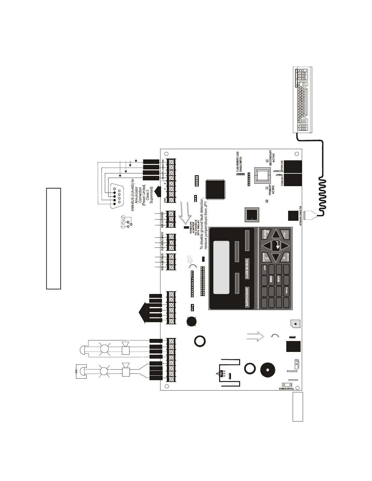
NAC #1 Shown Style Y (Class B) (Power-Limited, Class 2, Supervised)
NAC #2 Shown Style Z (Class A) (Power-Limited, Class 2, Supervised)
2.5 amps max. per circuit. Total available current 2.5 amps.
Nonsupervised Contact Ratings:
2.0 amps @ 30 VDC (resistive)
0.5 amps @ 30 VAC (resistive)
Contacts shown below in normal
condition (AC power with no alarm,
trouble or supervisory activity).
A Fail Safe Trouble
relay switches to the
NO position during
trouble conditions and
under loss of all power.
personal computer with FACP
Upload/Download Utility.
50 foot maximum within same room.
(Nonsupervised,
Power-limited (Class 2) Circuit)
Refer to the SLC Wiring
Manual for detailed
information on wiring
addressable devices
for Style 4, 6 and 7.
(Power- Limited, Class 2
Supervised Circuit)
ELR 4.7K, ½W
Battery
Basic System Connections
Notification Appliance Circuits
2 Programmable Relays &
1 Fixed Trouble Relay
EIA-232 to
personal computer
SLC Loop
NO NC C
NC NO C
NO NC C
Alarm* Trouble
Supervisory*
5 4 3 2 1
9 8 7 6
Green
Black
White
Red
NC NO C
24 VDC, nonpower-limited,
supervised, 18 Amp Hour max.
(* )Factory default relay programming
B
+
B
-
BA
+
A
-
A
X
M
T
6
R
C
V
5
G
N
D
8
D
T
R
7
Transformer
Connector
Nonpower-limited,
Supervised
Remove this jumper to enable
Supervisory relay when
4XTMF module is installed
NAC #1
-
+
B
+
B
-
1
4
A
+
A
-
23
+
+
NAC #2
B
+
B
-
A
+
A
-
+
+
+
56
78
CAUTION!
HIGH VOLTAGE
1
4
2
3
5
6
JP28
Cut JP28 to
supervise
4XTMF
J11
+
_
Charger Disable Jumper
(cut to disable FACP
onboard battery charger)
JP30
9050udlayo90.cdr
For specific UL wiring
information, refer to "UL
Power-limited Wiring
Requirements" on page 46