Page 6 of 28
®
DUAL
Integrated Fire Protection System
OWNER'S OPERATION & MAINTENANCE MANUAL
FM-0860-0-31F
4.3 PLACING SYSTEM IN SERVICE
1. Check all connections to the remote releasing control
panel.
2. Check all local audible devices.
3. Check all releasing conditions.
4. Check if NOVEC 1230 electric actuator (C) operates
after preset time delay.
5. Simulate a low cylinder pressure by shorting low cylinder
pressure switch (D) terminals.
6. Verify the active installation supervision switch on the
electric actuator (C).
CAUTION ! Activate the releasing circuit disable switch
before doing any tests on the system (see figure 6.2).
7. Verify that the system has been properly drained. Main
water supply control valve (D1) is CLOSED. Main drain
valve (D3) is OPEN. Emergency release valve (B10) is
CLOSED.
8. CLOSE main drain valve (D3).
9. OPEN priming valve (B1).
10. Reset the release control panel.
11. Restore supervisory pressure to sprinkler piping.
Note: On systems provided with an air pressure
maintenance device (air option style "B"), verify that the
½" by-pass valve (E8) in the air pressure maintenance
device trim is CLOSED and that both ¼" valves (E6 & E7)
are OPEN.
12. OPEN drain test valve (B6).
13. PARTIALLY OPEN main water supply control
valve (D1).
14. When full flow develops from the drain test valve (B6),
CLOSE the drain test valve and verify that there is no
flow from the drip check valve (B7) when the plunger is
pushed.
15. FULLY OPEN the main water supply control valve (D1).
16. Verify that the alarm test valve (B5) is CLOSED and that
all other valves are in their "normal" operating position.
17. Depress the plunger of the drip check valve (B7). No
water should flow when the plunger is pushed.
18. Check and repair all leaks.
19. Perform sequence of operation (refer to chapter 4.4).
20. Reset the remote releasing control panel.
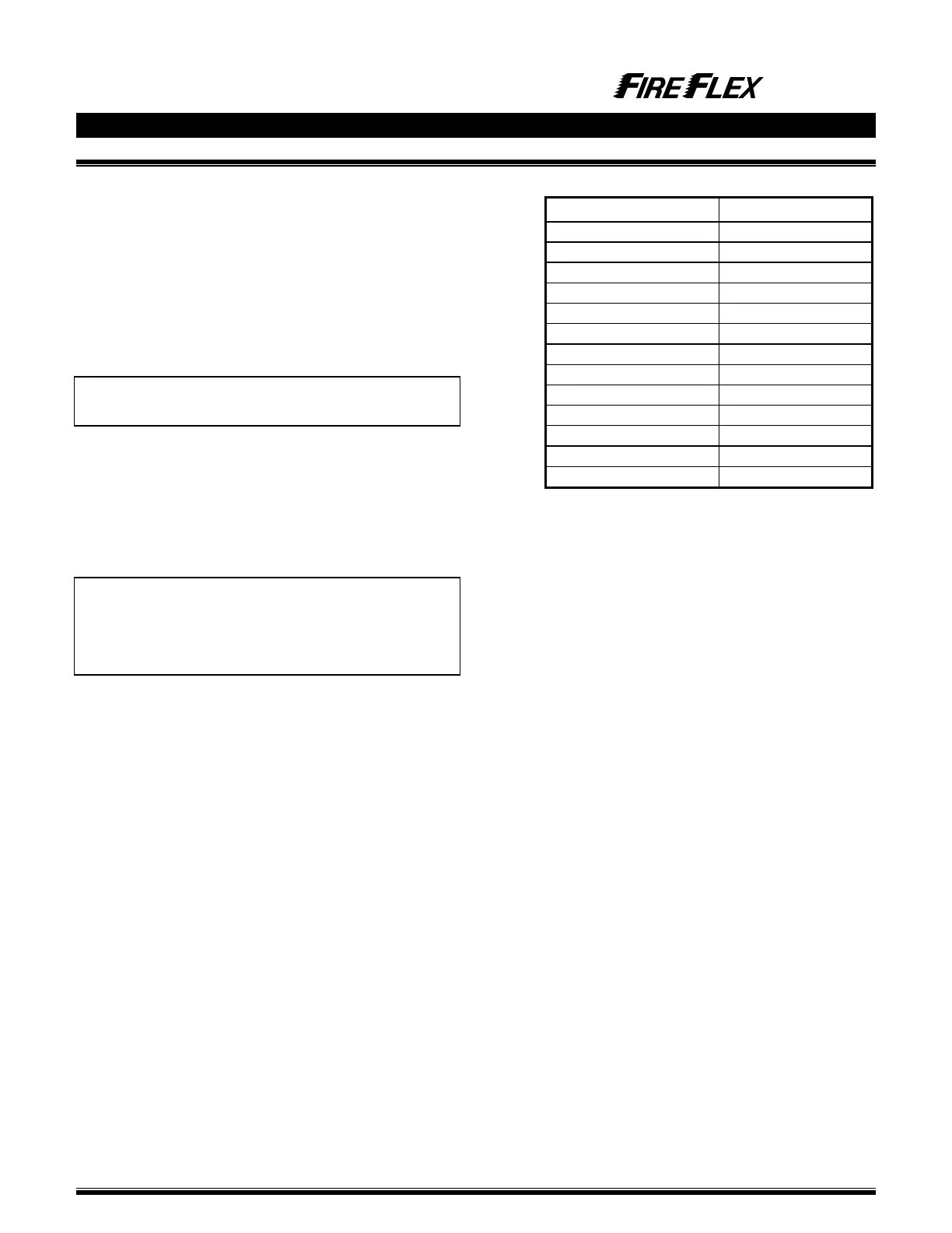
Table 4.1 - Cylinder pressure versus temperature
Cylinder pressure Temperature