®
DUAL Page 23 of 28
Integrated Fire Protection System
OWNER'S OPERATION & MAINTENANCE MANUAL
FM-0860-0-31F
6. CONTROLS
6.1 PRODUCT DESCRIPTION
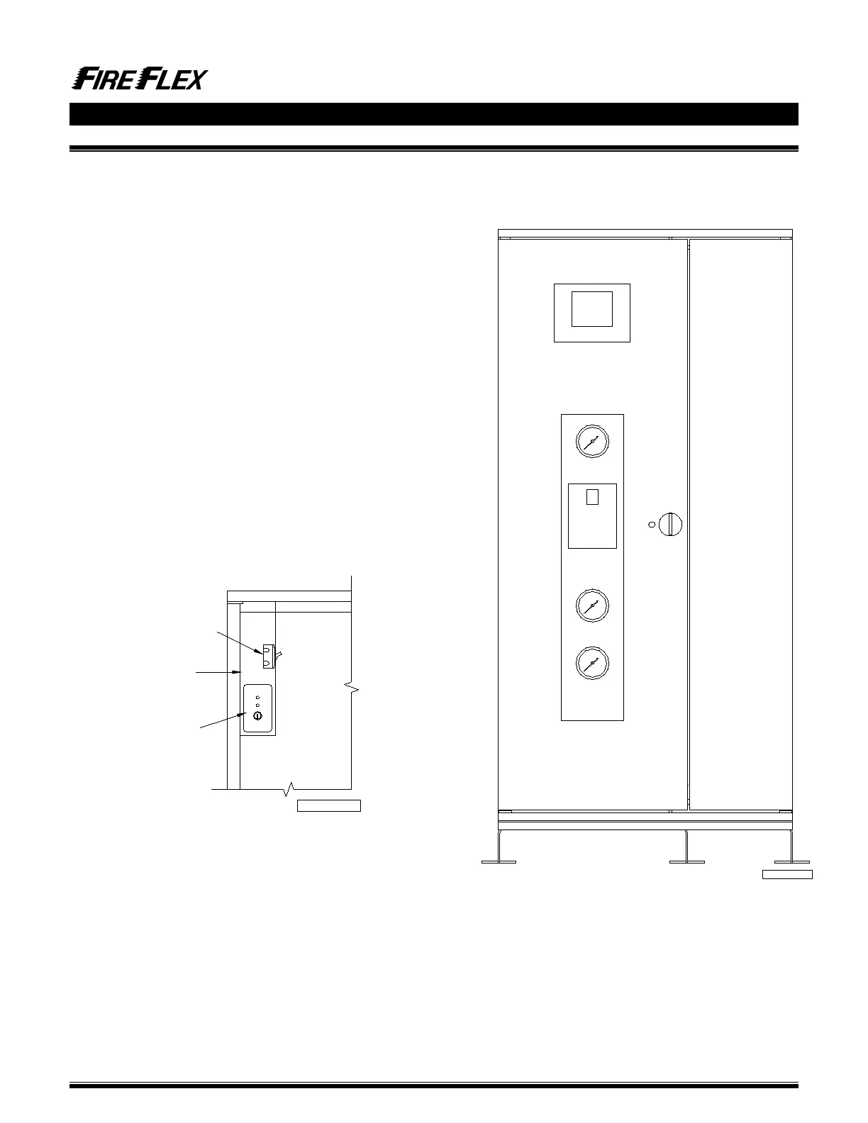
Once the left door opened, it give access to the electrical
junctions box and the releasing circuit disabled switch of the
NOVEC 1230 (refer to figure 7.1 FIELD WIRING DIAGRAM
for additional details).
6.2 REMOTE CONTROLED
FIREFLEX
®
DUAL
(Without integrated releasing control panel)
For application with
FIREFLEX
®
DUAL unit provided without
integrated releasing control panel, such as in retrofit
application where the unit is connected and controlled by a
central control panel already installed in the building or
premises, a field wiring junction box (see figure 6.2) is
provided. All electrical components in the trim (pressure
switches, electric actuator, etc.) are factory wired to a terminal
strip (TBA) for contractor's field wiring. The junction box
access is protected by a cover plate maintained in place with
screws.
The installing contractor should make sure the remote control
panel being used is both listed and programmed to handle the
required sequence of operation necessary to operate the
FIREFLEX
®
DUAL system.
Refer to section 1 GENERAL, appropriate standards and
Authority Having Jurisdiction for additional information.
Figure 6.2 - Equipment layout
Figure 6.1 - Cabinet doors assembly
FM-061H-0-68A-9
Junction box
TBA & TBB
Air compressor
isolation switch (E15)
NORMAL
DISABLE
RELEASING CIRCUIT
DISABLE SWITCH
Release circuit
disable switch
Cabinet doors on hinges
FM-061H-0-68A-3