Page 16 of 28
®
DUAL
Integrated Fire Protection System
OWNER'S OPERATION & MAINTENANCE MANUAL
FM-0860-0-31F
5. PREACTION AIR SUPPLIES
The sprinklers network of the preaction system uses air
pressure for supervisory purposes. The air supply can be
provided with either internal or external supervised air
supplies.
Two (2) styles of air supplies are available for the
FIREFLEX
®
DUAL unit depending on needs or
configurations. These air supplies are all factory assembled,
mounted in the cabinet and pressure tested. They are all
located in the top part of the cabinet, hung on mounting rails
above the valve trim. Here is the description of those
options:
♦ Air supply Style "A"
See figure 5.3.
Used only for the sprinkler piping network of the preaction
system. Air supply Style "A" includes the air compressor
mounted inside the
FIREFLEX
®
DUAL cabinet with its
supervisory trim and options. Compressor is factory piped
to the sprinkler piping system riser. It is available in three (3)
sizes:
1/6HP
1/3HP
1/2HP
All the above air compressors are oiless piston type without
reservoir and have open, single phase motor with internal
thermal protection and supply voltage of 120Vac, 60Hz or
220Vac, 50/60Hz.
♦ Air supply Style "B"
See figure 5.4.
Used only for the sprinkler piping network of the preaction
system, when an external air supply is provided by others
(either a compressor, plant air or dry nitrogen cylinders) and
piped to the air inlet port of the unit. Air supply Style "B"
provides an air pressure maintenance device (APMD) (E5)
trim, factory mounted in the
FIREFLEX
®
DUAL cabinet.
Note: When air supplies Style "B" is selected, the air
supply should be provided and installed by the sprinkler
contractor OUTSIDE of the FIREFLEX
®
DUAL cabinet.
It IS NOT provided with the unit.
5.1 AIR SUPPLY DESIGN AND SELECTION
The air supply compressor should be sized to automatically
establish the total required air pressure in 30 minutes.
External air supply should be provided with an air pressure
maintenance device (air supply Style "B") to regulate and
restrict the flow of supervisory air into the sprinkler system
piping.
WARNING ! Pressures other than the factory pressure
settings may affect the operation of the system.
Note: Selection of the proper air compressor size is the
responsibility of the installing contractor.
Table 5.1 - Compressor selection
Compressor
size
CFM
@
40 psi
120VAC
System
capacity
to pump 40 psi
in 30 minutes
220VAC
System
capacity
to pump 40 psi
in 30 minutes
1/6 HP
1.33
CFM
110 gallons 90 gallons
1/3 HP
2.61
CFM
215 gallons 170 gallons
1/2 HP
4.06
CFM
335 gallons 270 gallons
5.2 Air compressor AC power connection
(Air supply Style "A" only)
The motor must be protected against short circuit, overload
and excessive temperature rise. Fuses, motor protective
switches and thermal protective switches provide the
necessary protection in these circumstances.
Fuses only serve as a short circuit protection of the motor
(wiring fault), not as protection against overload. Those are
provided and wired by the electrical contractor.
An isolation switch (E15) is also provided in the
FIREFLEX
®
DUAL cabinet (see figure 6.2) and is factory
wired, allowing powering off the air compressor while some
maintenance work on the unit is done, without disturbing the
rest of the system.
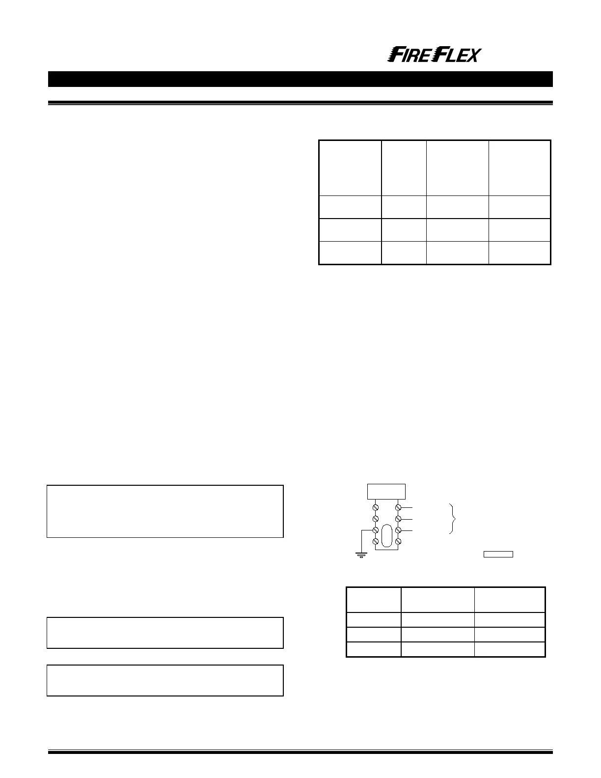
Connect non-energized AC power to the air compressor
input circuit (see figure 5.1).
Figure 5.1 - Wiring of power source
Table 5.1 - Compressor Amp rating
size
120VAC, 60Hz
220VAC, 50/60Hz
1/6 HP 6.6 A 3.3 A
1/3 HP 6.6 A 3.3 A
1/2 HP 8 A 4 A
NEUTRAL
GROUND
LINE
AC POWER SOURCE INPUT
4
3
2
1
TBB
AIR COMPRESSOR
120 / 220VAC
1/2 HP MAX
FM-076Z-0-7A