®
DUAL Page 9 of 28
Integrated Fire Protection System
OWNER'S OPERATION & MAINTENANCE MANUAL
FM-0860-0-31F
4.6 PLACING THE SYSTEM BACK IN SERVICE AFTER
OPERATION
See figures 4.5 & 4.6 at the end of the current section.
1. Remove the electric actuator (C) from the cylinder (A).
2. Remove cylinder (A) and send it to an authorized agent
for filling.
3. Reinstall the cylinder (A) inside the cabinet.
4. Reset the electric actuator (C) (refer to chapter 4.7).
5. Install the electric actuator (C) on the cylinder (A).
6. Check that the piping and nozzles have not been altered.
WARNING ! the optional mechanical release (J) SHALL
be in NORMAL position, handle upwards and safety pin
installed BEFORE installing it on the cylinder valve (B).
7. Verify that the system has been properly drained. Main
water supply control valve (D1) is CLOSED. Main drain
valve (D3) is OPEN. Emergency release valve (B10) is
CLOSED.
8. CLOSE main drain valve (D3).
9. OPEN priming valve (B1).
10. Restore supervisory pressure to sprinkler piping.
Note: On systems provided with an air pressure
maintenance device (air option style "B"), verify that the
½" by-pass valve (E8) in the air pressure maintenance
device trim is CLOSED and that both ¼" valves (E6 & E7)
are OPEN.
11. Reset the release control panel. Solenoid valve (F1)
should close.
12. OPEN drain test valve (B6).
13. PARTIALLY OPEN main water supply control
valve (D1).
14. When full flow develops from the drain test valve (B6),
CLOSE the drain test valve.
15. Verify that there is no flow from the drip check valve (B7)
when the plunger is pushed.
16. FULLY OPEN the main water supply control valve (D1).
17. Verify that the alarm test valve (B5) is CLOSED and that
all other valves are in their "normal" operating position.
18. Depress the plunger of the drip check valve (B7). No
water should flow from the drip check when the plunger
is pushed.
19. Check and repair all leaks.
20. Notify the Authority Having Jurisdiction, remote station
alarm monitors, and those in the affected area that the
system is back in service.
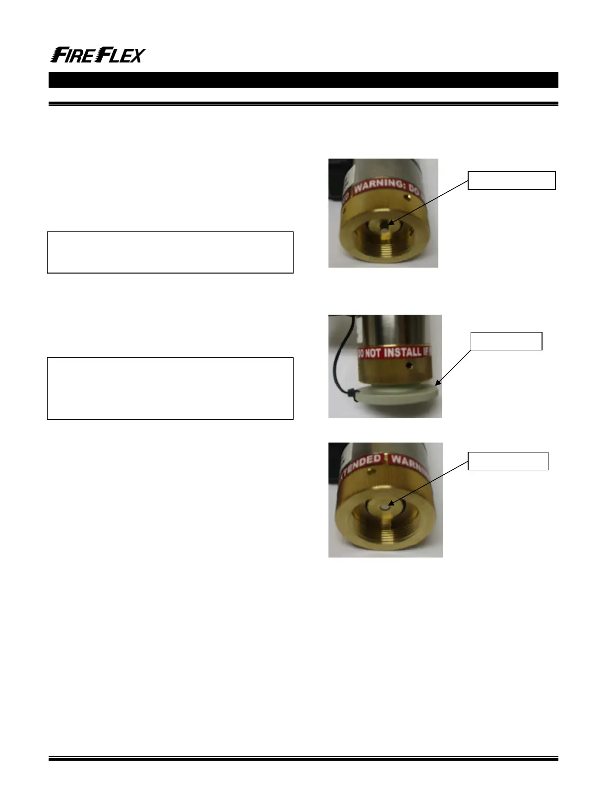
4.7 ELECTRIC ACTUATOR
When the electric actuator (C) gets energized, it stays in
the activated position (see figure 4.1).
Figure 4.1
Reset the actuator (C) to normal position by turning or
pushing the resetting tool (see figures 4.2 & 4.3).
Figure 4.2
Figure 4.3