®
DUAL Page 17 of 28
Integrated Fire Protection System
OWNER'S OPERATION & MAINTENANCE MANUAL
FM-0860-0-31F
5.3 OPERATION
♦ Air supply Style "A"
See figure 5.3.
To apply air pressure:
Establish AC power for the air compressor by activating the
correspondent circuit breaker at the electrical distribution
panel. Close the air inlet drain valve (E12). Start
compressor by activating the
compressor isolating
switch (E15) located within the unit (see figure 6.2).
If the air compressor motor fails to start or slows down under
load, shut the compressor off. Check that the supply voltage
agrees with the motor nameplate.
To close the air supply:
Turn off the compressor isolating switch (E15) (see
figure 6.2).
To adjust system air pressure (air compressor switch):
WARNING ! The cut-out/cut-in differential switch
adjustment screw (small screw to the right) is factory
set. DO NOT CHANGE ITS SETTING. Any
unauthorized modification of this setscrew adjustment
will void the system warranty and may also prevent the
system from operating normally.
The air compressor cut-off pressure switch (E2) (shown in
figure 5.2 with its cover removed) has its air compressor cut-
out adjustment screw (middle screw) factory set. This switch
should not need any adjustment but if necessary, follow the
instructions below:
1. Remove the cover of the air compressor cut-off
pressure switch (E2).
2. To raise the cut-out pressure of the air compressor,
turn the cut-out adjustment screw (middle screw) half
a turn CLOCKWISE.
3. Open the main drain valve (D3) and let the pressure
drop until the air compressor (E1) restarts. Check
pressure reading on the system pressure gauge (E3)
when the air compressor stops. Repeat until the
desired pressure is reached (refer to table 5.3). Once
all is done, replace the cover on the switch (E2).
Note: Do not turn the cut-out adjustment screw (middle
screw) all the way down in one shot. Proceed by steps.
Use the same method turning the cut-out adjustment
screw COUNTER-CLOCKWISE to lower the air
compressor cut-out pressure.
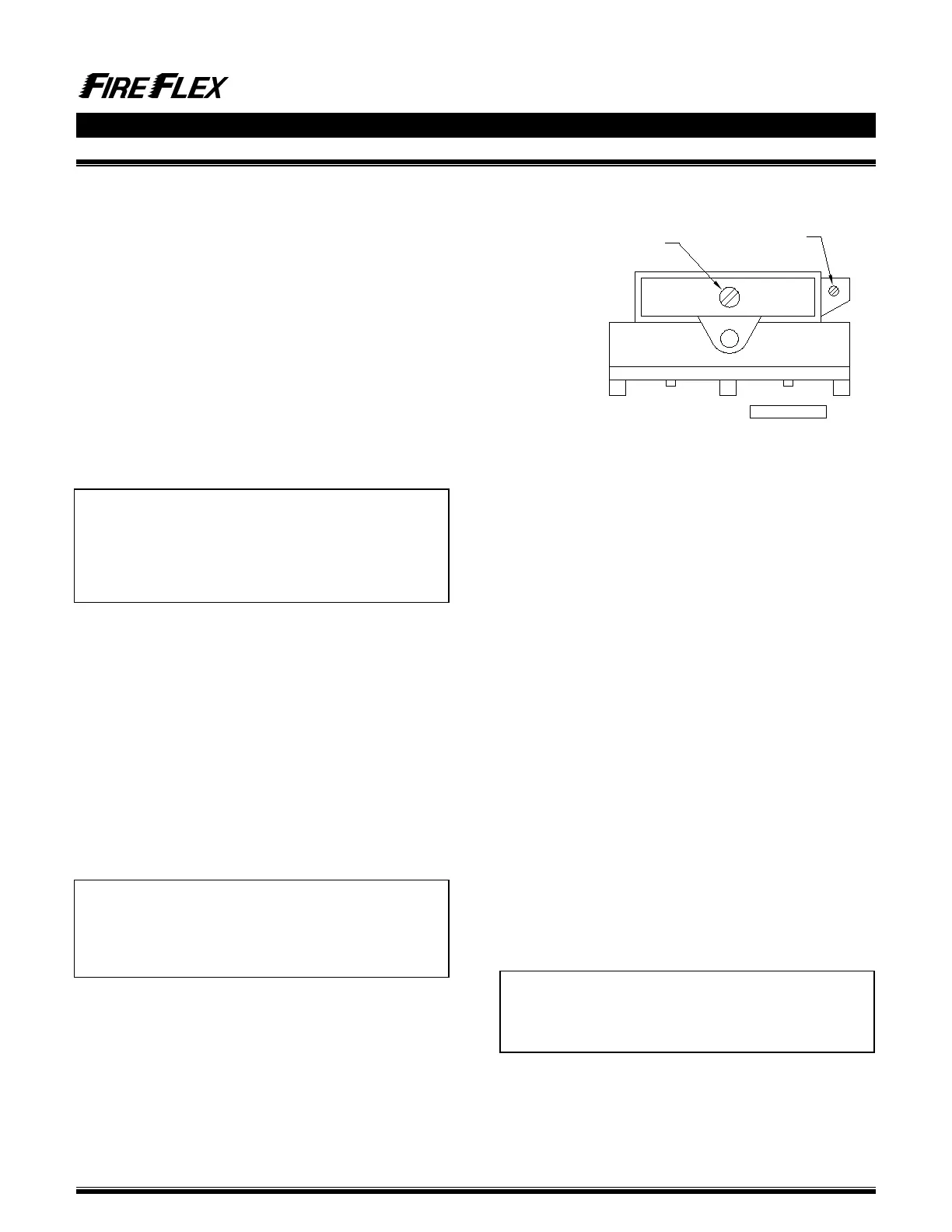
Figure 5.2 - Front view of the air compressor cut-off
pressure switch
♦ Air supply Style "B"
See figure 5.4.
To apply air pressure:
Turn on upstream air supply. If the unit is equipped with the
optional dehydrator (refer to section 5.5), close the air inlet
drain valve (E12) and open the air shut-off valve (E14).
Open APMD (E5) input valve (E6) by placing handle in line
with valve body then open APMD (E5) output valve (E7) by
placing handle in line with the valve body.
In order to accelerate filling of sprinkler piping by air
pressure, bypass valve (E8) can be opened by placing
handle in line with valve body while piping is initially filled by
the air compressor. This valve (E8) must then be closed
(handle crossways to valve body) and kept in this position
once the system is filled with air.
To close the air supply:
Close APMD output valve (E7) by placing handle crossways
to valve body then close APMD (E5) input valve (E6) by also
placing handle crossways to the valve body. Be sure bypass
valve (E8) is closed (handle crossways to valve body).
If the unit is equipped with optional dehydrator (refer to
section 5.5), close the air shut-off valve (E14).
To adjust system air pressure:
Be sure APMD (E5) input valve (E6) and output valve (E7)
are both open (handle in line with the valve body), and
bypass valve (E8) is closed (handle crossways to valve
body) prior to performing this operation. Loosen lock nut of
the DMPA (E5) and turn pressure adjustment nut clockwise
to increase air pressure or counter-clockwise to decrease
pressure. Tighten lock nut.
Note: Depending on site conditions, the internal filter of
the APMD (E5) may need maintenance on a regular
basis. Refer to Viking Data Sheet #127 for more
details.
Turn clockwise to increase
both cut-out and cut-in
pressure adjustment
Factory set
DO NOT CHANGE !
FM-072Q-0-109B