Page 20 of 28
®
DUAL
Integrated Fire Protection System
OWNER'S OPERATION & MAINTENANCE MANUAL
FM-0860-0-31F
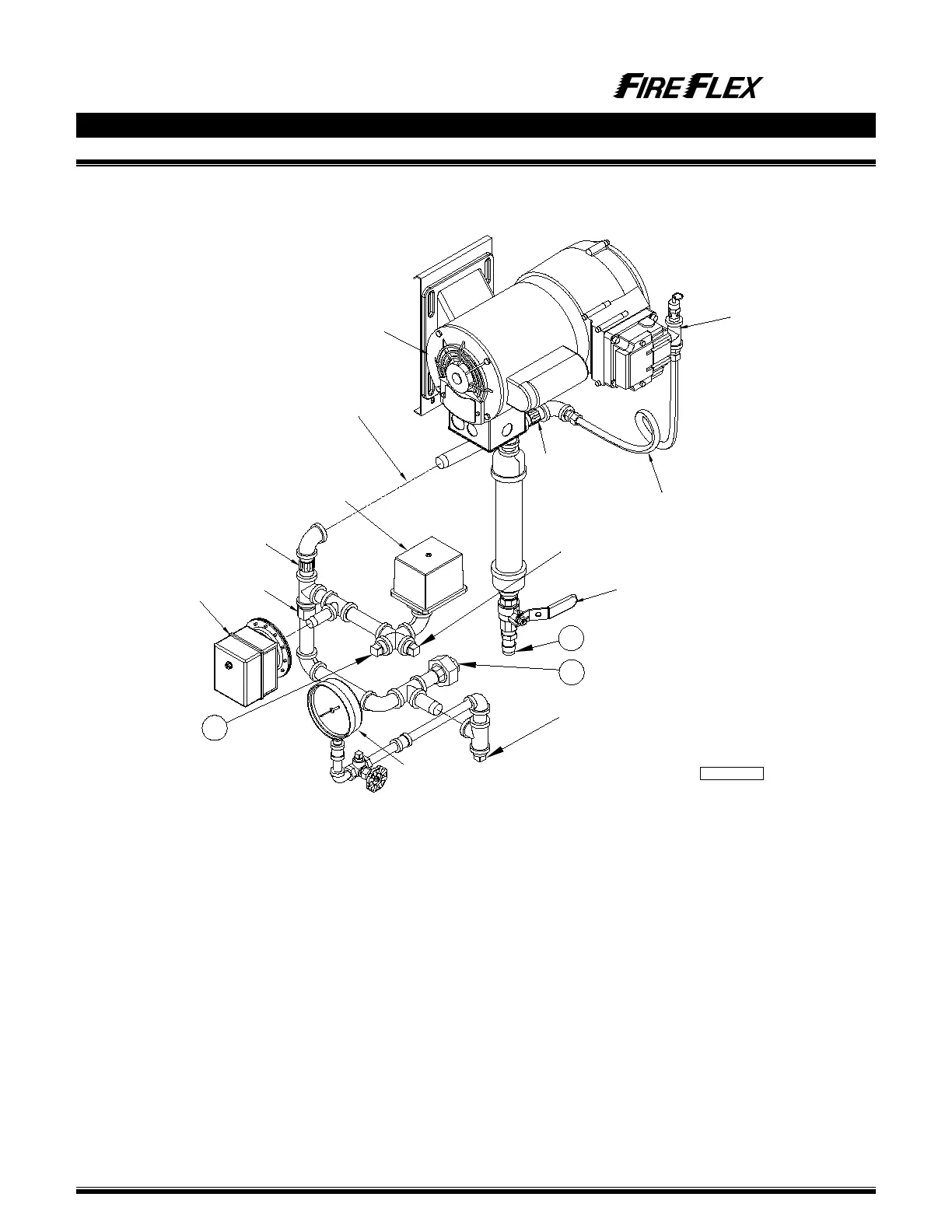
Figure 5.3 – Air supply Style "A"
(Cabinet mounted air compressor)
Air option components:
E1 Air compressor
E2 Air compressor "Cut-off" pressure switch
E3 System air pressure gauge
E4 Air supervisory pressure switch
E9 Float check valve
E10 Soft-seat check valve
E11 Air compressor check valve
E12 Air option drain valve
E13 Air supply accumulator
E15 Compressor isolating switch (not shown)
FM-061H-0-118CFM-061H-0-118C
1
CONTRACTOR'S
HYDROSTATIC TEST PORT
(system side)
2
E2
E11
TO DRAIN COLLECTOR
TO SPRINKLER RISER
E9
E10
Copper tubing
E12
E3
E1
This section replaced
by Dehydrator option
(when used)
TO OPTIONAL ACCELERATOR
(plugged when not used)
3
TO PNEUMATIC ACTUATOR
(plugged when not used)
E4
(plugged with
SureFire trim)
Pressure relief valve