Page 12 of 12
FIELD ASSEMBLY INSTRUCTIONS – MODEL 155/200/245/315 BLOWER
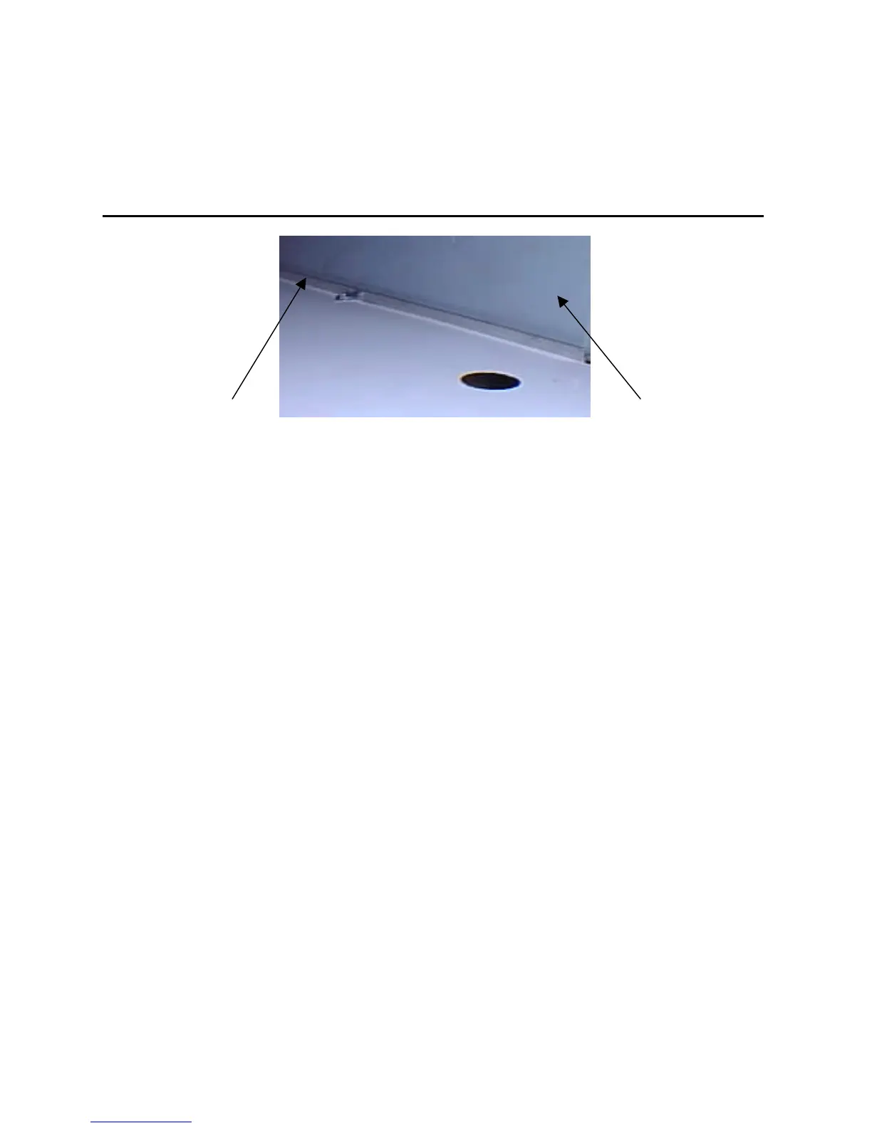
Air Deflector Flat Side of Blower
1. Position the Air Deflector, already in the cabinet, so that the upper lip sticks out of the
cabinet near the burner end. The lower ends of the Air Deflector are curved to direct the
path of the air from the blower to the chimney end. It also creates a barrier to prevent the
blower air from bypassing the body of the heat exchanger and going directly to the louvered
outlet. NOTE: Small gaps are acceptable between the air deflector, cabinet, and fire
chamber.
2. Place the blower in the square opening on the top of the heater so that the top of the air
deflector is pinched between the blower housing and edge of the cabinet opening. The
blower is placed so that the flat blower housing side is facing the burner. The blower is then
secured to the top of the heater with (4) cap screws through the weld nuts in the cabinet.
3. The fan limit switch attached to the 6 x 6 inch electrical box is factory located in a knockout
hole beside the blower. Tighten all electrical conduit connections and confirm wires are
secured in terminals.
4. The louvered panel and filler panel are interchangeable to control heated air discharge.
5. The stack cap fits both stack outlets and is to be secured to the opposite side of where the
chimney will connect. Use two screws to hold the cap or it may work loose over time.