Page 13 of 13
FIELD ASSEMBLY INSTRUCTIONS - BURNER
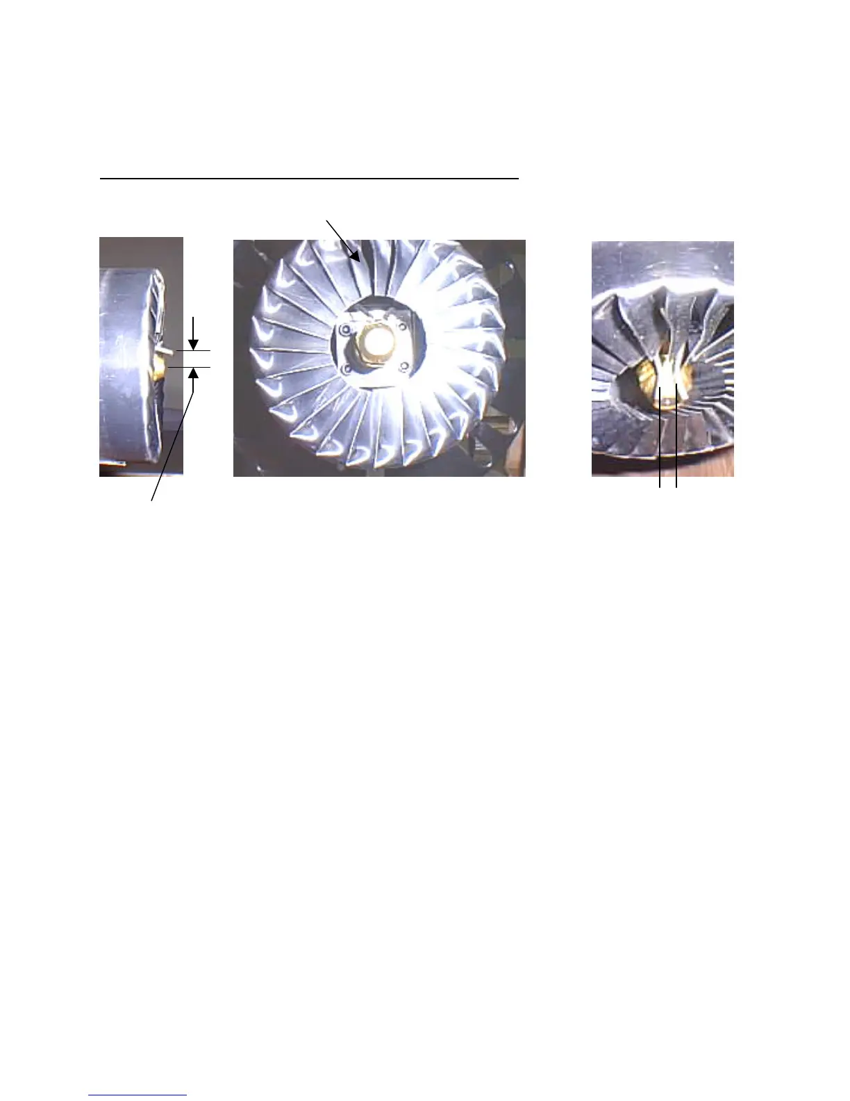
Upper fins are open to allow light to cad cell
7/16” center of nozzle to electrode 1/8” to 3/16” closest gap
1)
PRIOR TO INSTALLING BURNER, CHECK FOR SHIPPING DAMAGE TO
FLAME RETENTION HEAD AND IGNITION ELECTRODE ALIGNMENT
.
2) If components are not as shown you can make adjustments to the electrodes by removing the
hole plug on top of burner tube near mount flange. With screw driver, loosen the screw
holding the electrode clamping plate. Adjust electrodes as shown. Re-tighten clamp
screw. Do not over tighten or insulation on electrodes may crack. Examine electrode
position after tightening to be sure position has not changed. Replace hole plug.
3) The electrodes should not touch surrounding metal parts or be too close together as they will
restrict or divert the arc and not light the oil spray.
4) Position the large white insulation gasket(s) found in the blower carton between the furnace
door and the face of the heat exchanger. Some models may have them factory installed.
Pinch gasket with door and secure door with two nuts. Gaskets not used on model 350, 500.
5) Attach burner to furnace door/swing plate. Grasp burner by the mount flange and motor,
slip burner’s flange over studs on hinged burner door and secure with nuts.