17
PREPARE FOR INSTALLATION
Consult a qualifi ed professional installer / licensed contractor.
The in-ground post is designed primarily for installation with
a permanent underground gas supply. The power supply
cord is to be routed out the back.
To gain access to the inside of the post, unscrew and carefully
open the access plate on the rear of the post using a medium
Phillips-head screwdriver. Retain the screws.
A power supply is pre-mounted to the access plate. For ease
of installation, disconnect the power supply from the wire
harness extension. Locate the wires coming from the inside
of the post to the power supply and carefully disconnect (see
Fig. 17-1 and 17-2).
Important: Pull from the connectors (not the wires).
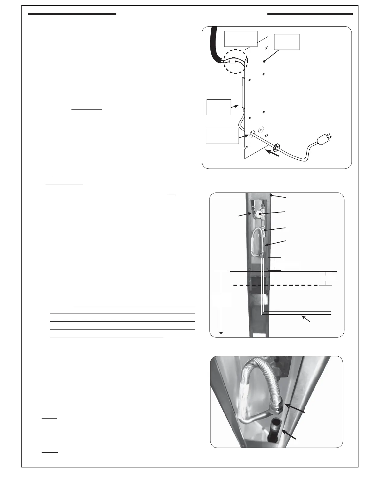
ROUTE POWER SUPPLY CORD
The power cord will need to be routed through the access
plate for later connection to a 120VAC (15 AMP minimum)
GFCI GROUNDED 3-wire receptacle.
1. Remove the knock-out disc at the bottom left of the
access plate with a large fl athead screwdriver. (Insert
the screwdriver into the notch provided in the center
of the knock-out.)
2. Remove the plastic power cord bushing attached to
the power cord.
3. Feed the power cord through the newly created hole.
4. Install the bushing onto the power cord and slide the
bushing up against the access plate knock-out hole
and snap into place. See Fig. 17-1.
ROUTE GAS SUPPLY (UNDERGROUND METHOD)
Note: This section addresses an underground gas supply
setup. To connect through the rear of the post,
reference the ROUTE FLEX CONNECTOR section of
PATIO-MOUNT INSTALLATION, and do not perform
the steps until after: attaching the extension post, and
installing the post / pouring the concrete.
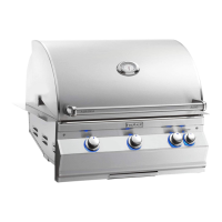
1. After running the underground gas supply line to the
planned grill location, dig a hole for the post and extension
approximately 18" deep and 10-12" in diameter.
Note: Run the gas supply line up from the bottom of
the hole (a little off center) so that it reaches to
approximately 4" above ground level.
Note: The actual depth of the hole should be such that
the cooking surface is 34-35" above ground level.
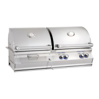
2. Verify that the gas supply line fi ts through the gas line
clearance hole in the bottom of the post (see Fig. 17-
3). The
clearance hole is the larger of the two holes in the bottom
of the post and is off center.
3. Verify that the fl ex connector coming from the inside of
the post will connect properly with the gas supply line.
Ground level
Concrete level
Post
Gas supply
route
Fig. 17-1 Access plate view & orientation
Access
plate
Power cord
knock-out
Power
supply
Wire
Connections
Fig. 17-2 In-ground install orientation
4" (approx.)
18"
(approx.)
3-5"
Wire
harness
extension
Flex connector
(w/ adapter)
Supply line
Fig. 17-3 Post interior detail
Flex connector
(w/ adapter)
Regulator
Back of timer valve
IN-GROUND POST INSTALLATION