18
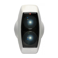
5.2 Receiver Status Indicators
Condition (LEFT HAND LED)
RECEIVER 1
STATUS LED
(MIDDLE LED)
RECEIVER 2
STATUS LED
FIRE RELAY
STATE
FAULT RELAY
STATE
Normal No Flash No Flash Open Closed
Fault (Trouble) Flashes AMBER
every 10 seconds
Flashes AMBER
every 10 seconds
Open Open
Fire (Alarm) Flashes RED every
10 seconds
Flashes RED every
10 seconds
Closed Closed
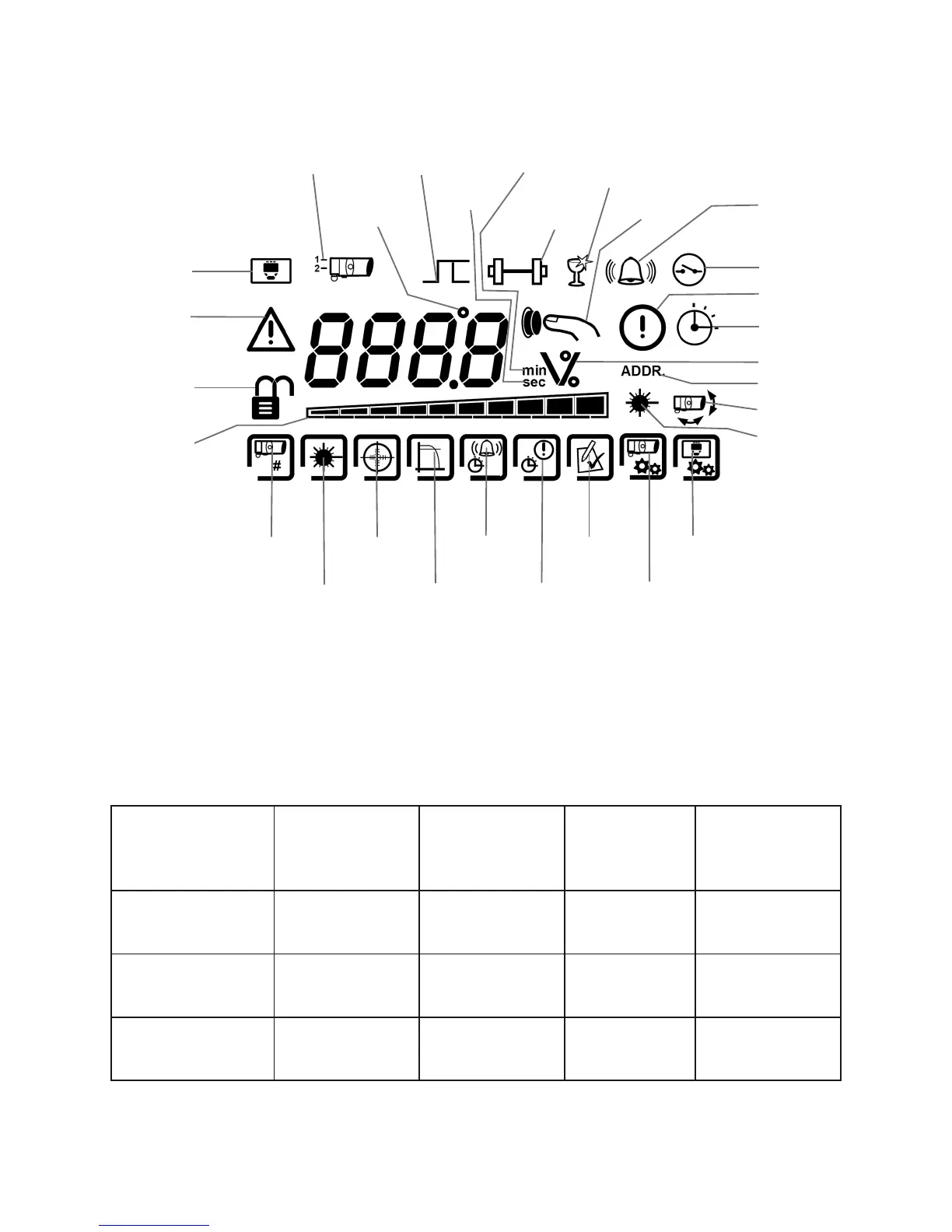
5.3 Controller Status Indicators
Latched /
Reset
Degrees
& LED
Setting
Receiver
Number
Controller
Setting
Warning
System Locked /
Unlocked
Bar Graph
Receiver
Find
LASER
Targeting
Beam
Alignment
Fire
Threshold
Delay
To Fire
Delay To
Fault
Fire
Test
Receiver
Settings
Controller
Settings
Seconds
Minutes
Signal
Strength
Compensation
Level
User
Prompt
Fire
External Reset
Fault
Busy
% / V
Address Setting
Alignment Mode
Laser
5. Display and Indicators
5.1 LCD Icon Layout
The Green and Amber LEDs flash during alignment to indicate alignment status. Refer to alignment procedure for
further information.
The Red LED will flash every 10 seconds when a fire is detected during normal operation.
System Controller Status LED (Right-hand LED) flashes green every 10 seconds.